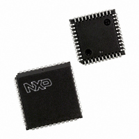
P87C591VFA/00,512 NXP Semiconductors, P87C591VFA/00,512 Datasheet - Page 119

P87C591VFA/00,512
Manufacturer Part Number
P87C591VFA/00,512
Description
IC 80C51 MCU 16K OTP 44-PLCC
Manufacturer
NXP Semiconductors
Series
87Cr
Datasheet
1.P87C591VFA00512.pdf
(160 pages)
Specifications of P87C591VFA/00,512
Core Processor
8051
Core Size
8-Bit
Speed
12MHz
Connectivity
CAN, EBI/EMI, I²C, UART/USART
Peripherals
POR, PWM, WDT
Number Of I /o
32
Program Memory Size
16KB (16K x 8)
Program Memory Type
OTP
Ram Size
512 x 8
Voltage - Supply (vcc/vdd)
4.75 V ~ 5.25 V
Data Converters
A/D 6x10b
Oscillator Type
Internal
Operating Temperature
-40°C ~ 85°C
Package / Case
44-PLCC
Processor Series
P87C5x
Core
80C51
Data Bus Width
8 bit
Data Ram Size
512 B
Interface Type
CAN, I2C, UART
Maximum Clock Frequency
12 MHz
Number Of Programmable I/os
32
Number Of Timers
3
Maximum Operating Temperature
+ 85 C
Mounting Style
SMD/SMT
3rd Party Development Tools
PK51, CA51, A51, ULINK2
Minimum Operating Temperature
- 40 C
On-chip Adc
10 bit, 6 Channel
Lead Free Status / RoHS Status
Lead free / RoHS Compliant
Eeprom Size
-
Lead Free Status / Rohs Status
Details
Other names
568-1256-5
935268182512
P87C591VFAA
935268182512
P87C591VFAA
Available stocks
Company
Part Number
Manufacturer
Quantity
Price
Company:
Part Number:
P87C591VFA/00,512
Manufacturer:
TI
Quantity:
8
Company:
Part Number:
P87C591VFA/00,512
Manufacturer:
NXP Semiconductors
Quantity:
10 000
Philips Semiconductors
16.1.7
Seven of the eight Timer T2 interrupt flags are located in
special function register TM2lR (see Section 16.1.7.1).
The eights flag is TM2CON.4.
The CT0l and CT1I flags are set during S4 of the cycle in
which the contents of Timer T2 are captured. CT0l is
scanned by the interrupt logic during S2, and CT1I is
scanned during S3. CT2l and CT3l are set during S6 and
are scanned during S4 and S5. The associated interrupt
requests are recognized during the following cycle. If these
flags are polled, a transition at CT0l or CT1I will be
recognized one cycle before a transition on CT2l or CT3l
since registers are read during S5. The CMI0, CMl1 and
CMl2 flags are set during S6 of the cycle following a match.
16.1.7.1
Table 78 Interrupt flag register (address C8H)
Table 79 Description of TM2IR bits
16.1.7.2
Table 80 Interrupt Priority Register 1 (address F8H)
Table 81 Description of IP1 bits
2000 Jul 26
Single-chip 8-bit microcontroller with CAN controller
T2OV
PT2
BIT
BIT
7
7
6
5
4
3
2
1
0
7
7
6
5
4
3
2
1
0
T
IMER
Interrupt Flag Register (TM2IR)
Interrupt Priority Register 1 (IP1)
T2 I
CMI2/CAN
CMI2/CAN
SYMBOL
SYMBOL
PCAN
PCAN
PCM1
PCM0
T2OV
NTERRUPT
PCT3
PCT2
PCT1
PCT0
CMI1
CMI0
CTI3
CTI2
CTI1
CTI0
PT2
6
6
F
T2: 16-bit overflow interrupt flag.
CM2: flag (for polling only). CAN: CAN interrupt flag (polling only).
CM1: interrupt flag.
CM0: interrupt flag.
CT3: interrupt flag.
CT2: interrupt flag.
CT1: interrupt flag.
CT0: interrupt flag.
T2 overflow interrupt(s) priority level.
CAN interrupt priority level.
T2 comparator 1 priority interrupt level.
T2 comparator 0 priority interrupt level.
T2 capture register 3 priority interrupt level.
T2 capture register 2 priority interrupt level.
T2 capture register 1 priority interrupt level.
T2 capture register 0 priority interrupt level.
LAG
PCM1
CMI1
R
5
5
EGISTER
TM2IR
PCM0
CMI0
4
4
119
CMl0 is scanned by the interrupt logic during S2; CMl1 and
CMl2 are scanned during S3 and S4. A match of CMl0 and
CMl1 will be recognized by the interrupt logic (or by polling
the flags) two cycles after the match takes place. A match
of CMl2 will cause no interrupt, this flag can be polled only.
The 16-bit overflow flag (T2OV) and the byte overflow flag
(T2BO) are set during S6 of the cycle in which the overflow
occurs. These flags are recognized by the interrupt logic
during the next cycle. Special function register lP1 (see
Section 16.1.7.2) is used to determine the Timer T2
interrupt priority. Setting a bit high gives that function a
high priority, and setting a bit low gives the function a low
priority. The functions controlled by the various bits of the
lP1 register are shown in Section 16.1.6.2.
PCT3
CTI3
3
3
DESCRIPTION
DESCRIPTION
PCT2
CTI2
2
2
PCT1
Preliminary Specification
CTI1
1
1
P8xC591
PCT0
CTI0
0
0


