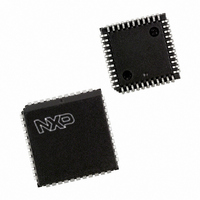
P87C591VFA/00,512 NXP Semiconductors, P87C591VFA/00,512 Datasheet - Page 130

P87C591VFA/00,512
Manufacturer Part Number
P87C591VFA/00,512
Description
IC 80C51 MCU 16K OTP 44-PLCC
Manufacturer
NXP Semiconductors
Series
87Cr
Datasheet
1.P87C591VFA00512.pdf
(160 pages)
Specifications of P87C591VFA/00,512
Core Processor
8051
Core Size
8-Bit
Speed
12MHz
Connectivity
CAN, EBI/EMI, I²C, UART/USART
Peripherals
POR, PWM, WDT
Number Of I /o
32
Program Memory Size
16KB (16K x 8)
Program Memory Type
OTP
Ram Size
512 x 8
Voltage - Supply (vcc/vdd)
4.75 V ~ 5.25 V
Data Converters
A/D 6x10b
Oscillator Type
Internal
Operating Temperature
-40°C ~ 85°C
Package / Case
44-PLCC
Processor Series
P87C5x
Core
80C51
Data Bus Width
8 bit
Data Ram Size
512 B
Interface Type
CAN, I2C, UART
Maximum Clock Frequency
12 MHz
Number Of Programmable I/os
32
Number Of Timers
3
Maximum Operating Temperature
+ 85 C
Mounting Style
SMD/SMT
3rd Party Development Tools
PK51, CA51, A51, ULINK2
Minimum Operating Temperature
- 40 C
On-chip Adc
10 bit, 6 Channel
Lead Free Status / RoHS Status
Lead free / RoHS Compliant
Eeprom Size
-
Lead Free Status / Rohs Status
Details
Other names
568-1256-5
935268182512
P87C591VFAA
935268182512
P87C591VFAA
Available stocks
Company
Part Number
Manufacturer
Quantity
Price
Company:
Part Number:
P87C591VFA/00,512
Manufacturer:
TI
Quantity:
8
Company:
Part Number:
P87C591VFA/00,512
Manufacturer:
NXP Semiconductors
Quantity:
10 000
Philips Semiconductors
2000 Jul 26
handbook, full pagewidth
handbook, full pagewidth
Single-chip 8-bit microcontroller with CAN controller
Rm = 0.5 - 3 k
C
R
Note:
Because the analog to digital converter has a sampled-data comparator, the input looks capacitive to a source. When a conversion is initiated, switch Sm
closes for 8 t
analog input to prevent a varying load to an analog source.
S
S
+ C
= Recommended < 9.6 k for 1 LSB @ 12 MHz
C
= 15 pF maximum
CY
(4
s @ 12 MHz crystal frequency) during which time capacitance C
R s
V in
V ANALOG
input
V digital
Fig.53 Effective Conversion Characteristic.
CODE
OUT
I N 1
Fig.52 A/D Input: Equivalent Circuit.
I N
101
100
011
010
001
000
QUANTIZATION ERROR
SYMMETRICAL QUANTIZATION ERROR
0
C s
q
q/2
q/2
Sm N 1
Sm N
MULTIPLEXER
2q
130
3q
Rm N 1
Rm N
q = LSB = 5 mV
S
4q
+ C
C
5q
is changed. It should be noted that the sampling causes the
C c
V in
V in
MHI054
MHI055
to comparator
Preliminary Specification
P8xC591


