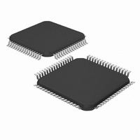
DSPIC33FJ32GS406-I/PT Microchip Technology, DSPIC33FJ32GS406-I/PT Datasheet - Page 255

DSPIC33FJ32GS406-I/PT
Manufacturer Part Number
DSPIC33FJ32GS406-I/PT
Description
IC MCU/DSP 32KB FLASH 64TQFP
Manufacturer
Microchip Technology
Series
dsPIC™ 33Fr
Specifications of DSPIC33FJ32GS406-I/PT
Core Processor
dsPIC
Core Size
16-Bit
Speed
40 MIPs
Connectivity
I²C, IrDA, LIN, SCI, SPI, UART/USART, USB
Peripherals
Brown-out Detect/Reset, QEI, POR, PWM, WDT
Number Of I /o
58
Program Memory Size
32KB (32K x 8)
Program Memory Type
FLASH
Ram Size
4K x 8
Voltage - Supply (vcc/vdd)
3 V ~ 3.6 V
Data Converters
A/D 16x10b
Oscillator Type
Internal
Operating Temperature
-40°C ~ 85°C
Package / Case
64-TFQFP
Core Frequency
40MHz
Embedded Interface Type
I2C, SPI, UART
No. Of I/o's
53
Flash Memory Size
32KB
Supply Voltage Range
3V To 3.6V
Rohs Compliant
Yes
Lead Free Status / RoHS Status
Lead free / RoHS Compliant
Eeprom Size
-
Lead Free Status / RoHS Status
Lead free / RoHS Compliant, Lead free / RoHS Compliant
Available stocks
Company
Part Number
Manufacturer
Quantity
Price
Company:
Part Number:
DSPIC33FJ32GS406-I/PT
Manufacturer:
Microchip Technology
Quantity:
10 000
- Current page: 255 of 418
- Download datasheet (3Mb)
17.0
FIGURE 17-1:
2010 Microchip Technology Inc.
dsPIC33FJ32GS406/606/608/610 and dsPIC33FJ64GS406/606/608/610
Note 1: This data sheet summarizes the features
INDXx
QEAx
QEBx
UPDNx
2: Some registers and associated bits
QUADRATURE ENCODER
INTERFACE (QEI) MODULE
(1)
(1)
(1)
Synchronize
of the dsPIC33FJ32GS406/606/608/610
and
families of devices. It is not intended to be
a comprehensive reference source. To
complement the information in this data
sheet, refer to Section 15. “Quadrature
Encoder Interface (QEI)” (DS70208) in
the “dsPIC33F/PIC24H Family Reference
Manual”, which is available from the
Microchip web site (www.microchip.com).
described in this section may not be avail-
able on all devices. Refer to Section 4.0
“Memory Organization” in this data
sheet for device-specific register and bit
information.
Sleep Input
Det
dsPIC33FJ64GS406/606/608/610
PCDOUT
UPDN_SRC
QUADRATURE ENCODER INTERFACE BLOCK DIAGRAM (x = 1 OR 2)
Programmable
Programmable
0
1
Programmable
0
1
Digital Filter
Digital Filter
Digital Filter
QEIxCON<11>
Existing Pin Logic
Up/Down
QEIM<2:0>
3
T
CY
Interface Logic
Quadrature
TQCS
Encoder
1
0
Mode Select
QEIM<2:0>
Note 1: The QEI1 module can be connected to the QEA1/QEB1/INDX1
Preliminary
3
TQGATE
or AQEA1/AQEB1/AINDX1 pins, which are controlled by clearing
or setting the ALTQIO bit in the FPOR Configuration register. See
Section 24.0 “Special Features” for more information.
1
0
2
This chapter describes the Quadrature Encoder Inter-
face (QEI) module and associated operational modes.
The QEI module provides the interface to incremental
encoders for obtaining mechanical position data.
The operational features of the QEI include:
• Three input channels for two phase signals and
• 16-bit up/down position counter
• Count direction status
• Position Measurement (x2 and x4) mode
• Programmable digital noise filters on inputs
• Alternate 16-bit Timer/Counter mode
• Quadrature Encoder Interface interrupts
These operating modes are determined by setting the
appropriate bits, QEIM<2:0> in (QEIxCON<10:8>).
Figure 17-1 depicts the Quadrature Encoder Interface
block diagram.
index pulse
Note:
16-bit Up/Down Counter
Max Count Register
D
CK
Comparator/
(POSxCNT)
(MAXxCNT)
Zero Detect
An ‘x’ used in the names of pins, control/
status bits and registers denotes a
particular Quadrature Encoder Interface
(QEI) module number (x = 1 or 2).
TQCKPS<1:0>
Q
Q
1, 8, 64, 256
Prescaler
2
Reset
Equal
DS70591C-page 255
QExIF
Event
Flag
Related parts for DSPIC33FJ32GS406-I/PT
Image
Part Number
Description
Manufacturer
Datasheet
Request
R

Part Number:
Description:
IC, DSC, 16BIT, 12KB, 40MHZ, 3.6V, DIP28
Manufacturer:
Microchip Technology
Datasheet:

Part Number:
Description:
Manufacturer:
Microchip Technology Inc.
Datasheet:

Part Number:
Description:
Manufacturer:
Microchip Technology Inc.
Datasheet:

Part Number:
Description:
Manufacturer:
Microchip Technology Inc.
Datasheet:

Part Number:
Description:
Manufacturer:
Microchip Technology Inc.
Datasheet:

Part Number:
Description:
Manufacturer:
Microchip Technology Inc.
Datasheet:

Part Number:
Description:
Manufacturer:
Microchip Technology Inc.
Datasheet:

Part Number:
Description:
Manufacturer:
Microchip Technology Inc.
Datasheet:

Part Number:
Description:
Manufacturer:
Microchip Technology Inc.
Datasheet:


