TOOLSTICK540DC Silicon Laboratories Inc, TOOLSTICK540DC Datasheet - Page 228
TOOLSTICK540DC
Manufacturer Part Number
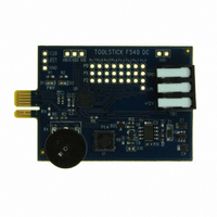
TOOLSTICK540DC
Description
DAUGHTER CARD TOOLSTICK F540
Manufacturer
Silicon Laboratories Inc
Series
ToolStickr
Type
MCUr
Datasheets
1.TOOLSTICK540DC.pdf
(274 pages)
2.TOOLSTICK540DC.pdf
(16 pages)
3.TOOLSTICK540DC.pdf
(12 pages)
Specifications of TOOLSTICK540DC
Contents
Daughter Card
Processor To Be Evaluated
C8051F54x
Processor Series
C8051F54x
Interface Type
USB
Operating Supply Voltage
2.7 V to 3.6 V
Lead Free Status / RoHS Status
Lead free / RoHS Compliant
For Use With/related Products
C8051F54x
For Use With
336-1345 - TOOLSTICK BASE ADAPTER336-1182 - ADAPTER USB DEBUG FOR C8051FXXX
Lead Free Status / Rohs Status
Lead free / RoHS Compliant
Other names
336-1717


C8051F54x
SFR Definition 23.1. CKCON: Clock Control
SFR Address = 0x8E; SFR Page = All Pages
228
Name
Reset
1:0
Bit
Type
7
6
5
4
3
2
Bit
SCA[1:0] Timer 0/1 Prescale Bits.
Name
T3MH
T2MH
T3ML
T2ML
T1
T0
T3MH
R/W
7
0
Timer 3 High Byte Clock Select.
Selects the clock supplied to the Timer 3 high byte (split 8-bit timer mode only).
0: Timer 3 high byte uses the clock defined by the T3XCLK bit in TMR3CN.
1: Timer 3 high byte uses the system clock.
Timer 3 Low Byte Clock Select.
Selects the clock supplied to Timer 3. Selects the clock supplied to the lower 8-bit timer
in split 8-bit timer mode.
0: Timer 3 low byte uses the clock defined by the T3XCLK bit in TMR3CN.
1: Timer 3 low byte uses the system clock.
Timer 2 High Byte Clock Select.
Selects the clock supplied to the Timer 2 high byte (split 8-bit timer mode only).
0: Timer 2 high byte uses the clock defined by the T2XCLK bit in TMR2CN.
1: Timer 2 high byte uses the system clock.
Timer 2 Low Byte Clock Select.
Selects the clock supplied to Timer 2. If Timer 2 is configured in split 8-bit timer mode,
this bit selects the clock supplied to the lower 8-bit timer.
0: Timer 2 low byte uses the clock defined by the T2XCLK bit in TMR2CN.
1: Timer 2 low byte uses the system clock.
Timer 1 Clock Select.
Selects the clock source supplied to Timer 1. Ignored when C/T1 is set to 1.
0: Timer 1 uses the clock defined by the prescale bits SCA[1:0].
1: Timer 1 uses the system clock.
Timer 0 Clock Select.
Selects the clock source supplied to Timer 0. Ignored when C/T0 is set to 1.
0: Counter/Timer 0 uses the clock defined by the prescale bits SCA[1:0].
1: Counter/Timer 0 uses the system clock.
These bits control the Timer 0/1 Clock Prescaler:
00: System clock divided by 12
01: System clock divided by 4
10: System clock divided by 48
11: External clock divided by 8 (synchronized with the system clock)
T3ML
R/W
6
0
T2MH
R/W
5
0
T2ML
R/W
Rev. 1.1
4
0
Function
T1M
R/W
3
0
T0M
R/W
2
0
1
0
SCA[1:0]
R/W
0
0
Related parts for TOOLSTICK540DC
Image
Part Number
Description
Manufacturer
Datasheet
Request
R

Part Number:
Description:
KIT TOOL EVAL SYS IN A USB STICK
Manufacturer:
Silicon Laboratories Inc
Datasheet:

Part Number:
Description:
TOOLSTICK DEBUG ADAPTER
Manufacturer:
Silicon Laboratories Inc
Datasheet:

Part Number:
Description:
TOOLSTICK BASE ADAPTER
Manufacturer:
Silicon Laboratories Inc
Datasheet:

Part Number:
Description:
TOOLSTICK DAUGHTER CARD
Manufacturer:
Silicon Laboratories Inc
Datasheet:

Part Number:
Description:
TOOLSTICK DAUGHTER CARD
Manufacturer:
Silicon Laboratories Inc
Datasheet:

Part Number:
Description:
TOOLSTICK DAUGHTER CARD
Manufacturer:
Silicon Laboratories Inc
Datasheet:

Part Number:
Description:
TOOLSTICK PROGRAMMING ADAPTER
Manufacturer:
Silicon Laboratories Inc
Datasheet:

Part Number:
Description:
TOOLSTICK DAUGHTER CARD
Manufacturer:
Silicon Laboratories Inc
Datasheet:

Part Number:
Description:
KIT STARTER TOOLSTICK
Manufacturer:
Silicon Laboratories Inc
Datasheet:

Part Number:
Description:
KIT UNIVERSITY TOOLSTICK STARTER
Manufacturer:
Silicon Laboratories Inc
Datasheet:

Part Number:
Description:
DAUGHTER CARD TOOLSTICK F330
Manufacturer:
Silicon Laboratories Inc
Datasheet:

Part Number:
Description:
CARD DAUGHTER UNIVRSTY TOOLSTICK
Manufacturer:
Silicon Laboratories Inc
Datasheet:

Part Number:
Description:
DAUGHTER CARD TOOLSTICK F582
Manufacturer:
Silicon Laboratories Inc
Datasheet:

Part Number:
Description:
DAUGHTER CARD TOOLSTICK F500
Manufacturer:
Silicon Laboratories Inc
Datasheet:

Part Number:
Description:
DAUGHTER CARD TOOLSTICK F560
Manufacturer:
Silicon Laboratories Inc
Datasheet: