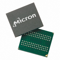
MT48H8M32LFB5-8 TR Micron Technology Inc, MT48H8M32LFB5-8 TR Datasheet - Page 15

MT48H8M32LFB5-8 TR
Manufacturer Part Number
MT48H8M32LFB5-8 TR
Description
IC SDRAM 256MBIT 125MHZ 90VFBGA
Manufacturer
Micron Technology Inc
Datasheet
1.MT48V8M32LFB5-8_IT_TR.pdf
(75 pages)
Specifications of MT48H8M32LFB5-8 TR
Format - Memory
RAM
Memory Type
Mobile SDRAM
Memory Size
256M (8Mx32)
Speed
125MHz
Interface
Parallel
Voltage - Supply
1.7 V ~ 1.95 V
Operating Temperature
0°C ~ 70°C
Package / Case
90-VFBGA
Lead Free Status / RoHS Status
Lead free / RoHS Compliant
Other names
557-1054-2
Figure 5: Low Power Extended Mode Register Table
Temperature Compensated Self Refresh
PDF: 09005aef80d460f2/Source: 09005aef80cd8d41
256Mb SDRAM x32_2.fm - Rev. G 6/05
Notes: 1. E13 and E12 (BA1 and BA0) must be “1, 0” to select the extended mode register (vs. the
The low-power extended mode register must be programmed with E7 through E11 set to
“0”. It must be loaded when all banks are idle and no bursts are in progress, and the con-
troller must wait the specified time before initiating any subsequent operation. Violating
either of these requirements results in unspecified operation. Once the values are
entered, the extended mode register settings will be retained even after exiting deep
power-down mode.
Temperature compensated self refresh (TCSR) allows the controller to program the
refresh interval during self refresh mode, according to the case temperature of the
Mobile device. This allows great power savings during self refresh during most operating
temperature ranges. Only during extreme temperatures would the controller have to
select the maximum TCSR level. This would guarantee data during self refresh.
Every cell in the DRAM requires refreshing due to the capacitor losing its charge over
time. The refresh rate is dependent on temperature. At higher temperatures a capacitor
loses charge quicker than at lower temperatures, requiring the cells to be refreshed more
often. Historically, during self refresh, the refresh rate has been set to accommodate the
worst case, or highest temperature range expected.
2. Default EMR values are full array for PASR, full drive strength.
3. RFU: reserved for future use.
4. E4 and E3 are “Don’t Care.”
base mode register).
E6
0
0
1
1
E5
0
1
0
1
BA1
1
E13
13
Driver Strength
Full Strength 2
Half Strength
RFU
RFU
1
0
BA0
12
E12
All must be set to "0"
11
A11
E11
15
10
A10
E10
9
A9
E9
8
A8
E8
7
E4
A7 A6 A5 A4 A3
E7 E6 E5 E4 E3
0
Micron Technology, Inc., reserves the right to change products or specifications without notice.
6
DS
E3
0
5
Must be set to "0"
0
4
E2
0
0
0
0
1
1
1
1
0
3
E1
0
0
1
1
0
0
1
1
A2 A1 A0
256Mb: x32 Mobile SDRAM
E2 E1 E0
2
PASR
E0
0
1
0
1
0
1
0
1
1
Self Refresh Coverage
Four Banks 2
Two Banks (Bank 0,1)
One Bank (Bank 0)
RFU 3
RFU
1/2 Bank (Bank 0)
1/4 Bank (Bank 0)
RFU
0
Address Bus
Low Power
Extended Mode
Register (Ex)
©2003 Micron Technology, Inc. All rights reserved.
Register Definition


