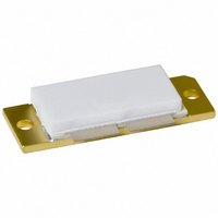
BLF872,112 NXP Semiconductors, BLF872,112 Datasheet

BLF872,112
Specifications of BLF872,112
934058888112
BLF872
BLF872
Related parts for BLF872,112
BLF872,112 Summary of contents
Page 1
BLF872 UHF power LDMOS transistor Rev. 01 — 20 February 2006 1. Product profile 1.1 General description A 300 W LDMOS RF power transistor for broadcast transmitter applications and industrial applications. The transistor can deliver 250 W broadband over the ...
Page 2
Philips Semiconductors 1.3 Applications Communication transmitter applications in the UHF band Industrial applications in the UHF band 1.4 Quick reference data Table 1: Typical RF performance at V test circuit. Mode of operation CW, class AB 2-tone, class AB PAL ...
Page 3
Philips Semiconductors 4. Limiting values Table 4: Limiting values In accordance with the Absolute Maximum Rating System (IEC 60134). Symbol Parameter V drain-source voltage DS V gate-source voltage GS T storage temperature stg T junction temperature j 5. Thermal characteristics ...
Page 4
Philips Semiconductors Fig 1. Output capacitance C 7. Application information Table 7: RF performance in a common-source 860 MHz narrowband test circuit unless otherwise specified. h Mode of operation f (MHz) 2-tone, class ...
Page 5
Philips Semiconductors 860 MHz Fig 2. CW power gain G , drain efficiency p typical values (dB) 14 IMD3 IMD5 100 150 ...
Page 6
Philips Semiconductors (dB IMD3 HI 8 IMD3 IMD at 4.3 MHz from frequency center. Fig 5. DVB-T (8K OFDM) power gain G order intermodulation distortion (high-frequency component ...
Page 7
Philips Semiconductors 7.1 Broadband operation data Measured in a common-source broadband (470 MHz to 860 MHz) test circuit. 300 P P o(sync)M (W) 200 P L(AV) 100 0 400 500 600 700 0.9 ...
Page 8
Philips Semiconductors 7.3 Reliability 7 10 Years (7) ( TTF; 0.1 % failure fraction; best estimate values. ( 100 110 ...
Page 9
Philips Semiconductors Table 8: List of components For test circuit, see Figure 10, 11 Component Description C15, C16 ceramic capacitor C17, C18 electrolytic capacitor C20 multilayer ceramic chip capacitor C21 tekelec trimmer C22 multilayer ceramic chip capacitor C23 multilayer ceramic ...
Page 10
G1(test) C30 R5 R3 C28 C24 R1 C26 L12 L13 50 C25 B2 C23 L13 L12 C27 R2 C32 C29 R4 R6 C31 +V G2(test) Fig 10. Class-AB common-source broadband test circuit L10 L2 L11 ...
Page 11
Fig 11. Printed-circuit board for class-AB broadband test circuit 95 mm 001aad753 ...
Page 12
C30 +V G1(test C28 R1 B2 L13 L12 C26 C23 C24 C25 C32 C27 L12 10 mm L13 broadband R2 BLF872 input C29 C31 G2(test) Fig 12. Component layout for class-AB broadband test circuit 32 ...
Page 13
Philips Semiconductors 9. Package outline Flanged LDMOST ceramic package; 2 mounting holes; 4 leads DIMENSIONS (millimetre dimensions are derived from the original inch dimensions) UNIT 6.6 10.55 0.15 30.5 mm ...
Page 14
Philips Semiconductors 10. Abbreviations Table 9: Acronym CDMA CW DVB EDGE ESR EVM GSM IMD LDMOS OFDM PCB PEP RF SMD TTF VSWR 11. Revision history Table 10: Revision history Document ID Release date BLF872_1 20060220 BLF872_1 Product data sheet ...
Page 15
Philips Semiconductors 12. Data sheet status [1] Level Data sheet status Product status I Objective data Development II Preliminary data Qualification III Product data Production [1] Please consult the most recently issued data sheet before initiating or completing a design. ...
Page 16
Philips Semiconductors 17. Contents 1 Product profi 1.1 General description ...


