CYIL1SM4000AA-GDC Cypress Semiconductor Corp, CYIL1SM4000AA-GDC Datasheet - Page 9
CYIL1SM4000AA-GDC
Manufacturer Part Number
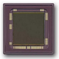
CYIL1SM4000AA-GDC
Description
SENSOR IMAGE 4MP CMOS 127-PGA
Manufacturer
Cypress Semiconductor Corp
Type
CMOS Imagingr
Datasheet
1.CYIL1SM4000-EVAL.pdf
(32 pages)
Specifications of CYIL1SM4000AA-GDC
Package / Case
127-PGA
Pixel Size
12µm x 12µm
Active Pixel Array
2048H x 2048V
Frames Per Second
15
Voltage - Supply
2.5V, 3.3V
Operating Supply Voltage
2.5 V
Maximum Operating Temperature
+ 60 C
Minimum Operating Temperature
0 C
Image Size
2048 H x 2048 V
Color Sensing
Monochrome
Package
127CPGA
Operating Temperature
0 to 60 °C
Lead Free Status / RoHS Status
Contains lead / RoHS non-compliant
Lead Free Status / RoHS Status
Lead free / RoHS Compliant, Contains lead / RoHS non-compliant
Other names
LUPA-4000-M
LUPA-4000-M
LUPA-4000-M


Non Destructive Readout (NDR)
The sensor can also be read out in a non destructive way. After
a pixel is initially reset, it can be read multiple times without
resetting. The initial reset level and all intermediate signals can
be recorded. High light levels saturate the pixels quickly, but a
useful signal is obtained from the early samples. For low light
levels, use the latest samples.
Figure 10. Principle of NDR
An active pixel array is read multiple times and reset only once.
The external system intelligence takes care of the interpretation
of the data.
tages of non-destructive readout.
Table 2. Advantages and Disadvantages of NDR
Document Number: 38-05712 Rev. *F
Low noise, because it is true
corrrlated double sampling
(CDS).
High sensitivity, because the
conversion capacitance is kept
low.
High dynamic range, because
the results includes signal for
short and long integrations
times.
Advantages
Table 2
summarizes the advantages and disadvan-
System memory required to
record the reset level and the
intermediate samples.
Requires multiples readings
of each pixel, thus higher data
throughput.
Requires system level digital
calculations.
Disadvantages
time
Operation and Signaling
The signals are classified into the following groups:
■
■
■
■
■
Power Supplies and Ground
Every module on chip including column amplifiers, output
stages, digital modules, and drivers has its own power supply
and ground. Off chip, the grounds can be combined, but not all
power supplies may be combined. This results in several
different power supplies, but this is required to reduce electrical
cross-talk and improve shielding, dynamic range, and output
swing.
On chip, the ground lines of every module are kept separately to
improve shielding and electrical cross talk between them.
An overview of the supplies is given in
on page 4. The maximum currents mentioned in the
specifications table are peak currents which occur once per
frame (except for Vres_ds in multiple slope mode). All power
supplies should be able to deliver these currents except for
Vmem_l and Vpre_l, which must be able to sink this current.
The maximum peak current for Vpix should not be higher than
500 mA. Note that no power supply filtering on chip is
implemented and noise on these power supplies can contribute
immediately to the noise on the signal. The voltage supplies Vpix
and Vaa must be noise free.
Startup Sequence
The LUPA 4000 goes in latch-up (draw high current) when all
power supplies are turned on simultaneously. The sensor comes
out of latch-up and starts working normally as soon as it is
clocked. A power supply current limit of 400 mA is recommended
to avoid damage to the sensor. Avoid the time that the device is
in the latch-up state, so clocking of the sensor should start as
soon as the system is turned on.
To avoid latch-up of the sensor, follow this sequence:
1. Apply Vdd
2. Apply clocks and digital pulses to the sensor to count 1024
3. Apply other supplies
Power supplies and grounds
Biasing and analog signals
Pixel array signals
Digital signals
Test signals
clock_x and 2048 clock_y pulses to empty the shift registers
CYIL1SM4000AA
Electrical Specifications
Page 9 of 32
Related parts for CYIL1SM4000AA-GDC
Image
Part Number
Description
Manufacturer
Datasheet
Request
R

Part Number:
Description:
Manufacturer:
Cypress Semiconductor Corp
Datasheet:
Part Number:
Description:
Manufacturer:
Cypress Semiconductor Corp
Datasheet:
Part Number:
Description:
Manufacturer:
Cypress Semiconductor Corp
Datasheet:
Part Number:
Description:
Manufacturer:
Cypress Semiconductor Corp
Datasheet:
Part Number:
Description:
Manufacturer:
Cypress Semiconductor Corp
Datasheet: