CYIL1SM4000AA-GDC Cypress Semiconductor Corp, CYIL1SM4000AA-GDC Datasheet - Page 31
CYIL1SM4000AA-GDC
Manufacturer Part Number
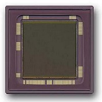
CYIL1SM4000AA-GDC
Description
SENSOR IMAGE 4MP CMOS 127-PGA
Manufacturer
Cypress Semiconductor Corp
Type
CMOS Imagingr
Datasheet
1.CYIL1SM4000-EVAL.pdf
(32 pages)
Specifications of CYIL1SM4000AA-GDC
Package / Case
127-PGA
Pixel Size
12µm x 12µm
Active Pixel Array
2048H x 2048V
Frames Per Second
15
Voltage - Supply
2.5V, 3.3V
Operating Supply Voltage
2.5 V
Maximum Operating Temperature
+ 60 C
Minimum Operating Temperature
0 C
Image Size
2048 H x 2048 V
Color Sensing
Monochrome
Package
127CPGA
Operating Temperature
0 to 60 °C
Lead Free Status / RoHS Status
Contains lead / RoHS non-compliant
Lead Free Status / RoHS Status
Lead free / RoHS Compliant, Contains lead / RoHS non-compliant
Other names
LUPA-4000-M
LUPA-4000-M
LUPA-4000-M


Appendix B: Frequently Asked Questions
Q: How does the dual (multiple) slope extended dynamic range mode work?
A: The green lines in
determined by the amount of light at each pixel (the more light the steeper the slope). When the pixels reach the saturation level, the
analog signal does not change despite further exposure. Without any double slope, pulse pixels p3 and p4 reaches saturation before
the sample moment of the analog values, no signal is acquired without double slope. When double slope is enabled a second reset
pulse is given (blue line) at a certain time before the end of the integration time. This double slope reset pulse resets the analog signal
of the pixels below this level to the reset level. After the reset the analog signal starts to decrease with the same slope as before the
double slope reset pulse. If the double slope reset pulse is placed at the end of the integration time (90% for instance) the analog
signal that reaches the saturation levels are not saturated anymore (this increases the optical dynamic range) at read out. Note that
pixel signals above the double slope reset level are not influenced by this double slope reset pulse (p1 and p2).
Document Number: 38-05712 Rev. *F
Reset pulse
Total integration time
Figure 27
are the analog signal on the photodiode, which decrease as a result of exposure. The slope is
Double slope reset pulse
Figure 27. Dual Slope Diagram
Read out
p1
p4
p2
p3
Double slope reset time (usually 5-
10% of the total integration time)
Reset level 1
Reset level 2
Saturation level
CYIL1SM4000AA
Page 31 of 32
Related parts for CYIL1SM4000AA-GDC
Image
Part Number
Description
Manufacturer
Datasheet
Request
R

Part Number:
Description:
Manufacturer:
Cypress Semiconductor Corp
Datasheet:
Part Number:
Description:
Manufacturer:
Cypress Semiconductor Corp
Datasheet:
Part Number:
Description:
Manufacturer:
Cypress Semiconductor Corp
Datasheet:
Part Number:
Description:
Manufacturer:
Cypress Semiconductor Corp
Datasheet:
Part Number:
Description:
Manufacturer:
Cypress Semiconductor Corp
Datasheet: