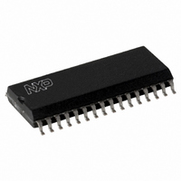
CLRC63201T/0FE,112 NXP Semiconductors, CLRC63201T/0FE,112 Datasheet - Page 29

CLRC63201T/0FE,112
Manufacturer Part Number
CLRC63201T/0FE,112
Description
IC I.CODE HS READER 32-SOIC
Manufacturer
NXP Semiconductors
Series
I-Coder
Specifications of CLRC63201T/0FE,112
Rf Type
Read Only
Frequency
13.56MHz
Features
ISO14443-A, ISO14443-B, ISO15693, ISO18000-3
Package / Case
32-SOIC (0.300", 7.50mm Width)
Product
RFID Readers
Operating Temperature Range
- 25 C to + 85 C
Lead Free Status / RoHS Status
Lead free / RoHS Compliant
Lead Free Status / RoHS Status
Lead free / RoHS Compliant, Lead free / RoHS Compliant
Other names
568-2199-5
935269690112
CLRC632
CLRC63201TD
935269690112
CLRC632
CLRC63201TD
Available stocks
Company
Part Number
Manufacturer
Quantity
Price
Company:
Part Number:
CLRC63201T/0FE,112
Manufacturer:
IR
Quantity:
3 400
Part Number:
CLRC63201T/0FE,112
Manufacturer:
NXP/恩智浦
Quantity:
20 000
NXP Semiconductors
CLRC632_35
Product data sheet
PUBLIC
9.6.3 Standby mode
9.6.4 Automatic receiver power-down
9.7.1 Hard power-down phase
9.7.2 Reset phase
9.7 StartUp phase
The Standby mode is immediately entered when the Control register StandBy bit is set. All
internal current sinks, including the internal digital clock buffer are switched off. However,
the oscillator buffer is not switched off.
The digital input buffers are not separated by the input pads, keeping their functionality
and the digital output pins do not change their state. In addition, the oscillator does not
need time to wake-up.
After resetting the Control register StandBy bit, it takes four clock cycles on pin OSCIN for
Standby mode to exit. Resetting bit StandBy does not immediately clear it. It is
automatically cleared when the Standby mode is exited.
It is a power saving feature to switch off the receiver circuit when it is not needed. Setting
bit RxAutoPD = logic 1, automatically powers down the receiver when it is not in use.
Setting bit RxAutoPD = logic 0, keeps the receiver continuously powered up.
The events executed during the StartUp phase are shown in
The hard power-down phase is active during the following cases:
The reset phase automatically follows the Hard power-down. Once the oscillator is
running stably, the reset phase takes 512 clock cycles. During the reset phase, some
register bits are preset by hardware. The respective reset values are given in the
description of each register (see
Remark: When the internal oscillator is used, time (t
become stable. This is because the internal oscillator is supplied by V
cycles will not be detected by the internal logic until V
Fig 10. The StartUp procedure
•
•
a Power-On Reset (POR) caused by power-up on pins DVDD or AVDD activated
when V
a HIGH-level on pin RSTPD which is active while pin RSTPD is HIGH. The HIGH level
period on pin RSTPD must be at least 100 s (t
necessarily result in the reset phase (t
RSTPD is not critical because pin RSTPD is a Schmitt trigger input.
states
DDD
or V
DDA
Hard power-
down phase
Rev. 3.5 — 10 November 2009
t
RSTPD
is below the digital reset threshold.
Multiple protocol contactless reader IC (MIFARE/I-CODE1)
073935
Section 10.5 on page
StartUp phase
Reset phase
reset
t
reset
). The rising or falling edge slew rate on pin
PD
osc
DDA
50).
) is required for the oscillator to
100 s). Shorter phases will not
is stable.
Figure
Initialising
phase
t
init
10.
CLRC632
DDA
© NXP B.V. 2009. All rights reserved.
and any clock
001aak613
ready
29 of 126


