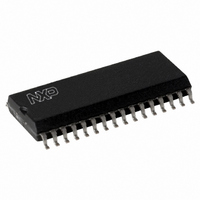
CLRC63201T/0FE,112 NXP Semiconductors, CLRC63201T/0FE,112 Datasheet - Page 26

CLRC63201T/0FE,112
Manufacturer Part Number
CLRC63201T/0FE,112
Description
IC I.CODE HS READER 32-SOIC
Manufacturer
NXP Semiconductors
Series
I-Coder
Specifications of CLRC63201T/0FE,112
Rf Type
Read Only
Frequency
13.56MHz
Features
ISO14443-A, ISO14443-B, ISO15693, ISO18000-3
Package / Case
32-SOIC (0.300", 7.50mm Width)
Product
RFID Readers
Operating Temperature Range
- 25 C to + 85 C
Lead Free Status / RoHS Status
Lead free / RoHS Compliant
Lead Free Status / RoHS Status
Lead free / RoHS Compliant, Lead free / RoHS Compliant
Other names
568-2199-5
935269690112
CLRC632
CLRC63201TD
935269690112
CLRC632
CLRC63201TD
Available stocks
Company
Part Number
Manufacturer
Quantity
Price
Company:
Part Number:
CLRC63201T/0FE,112
Manufacturer:
IR
Quantity:
3 400
Part Number:
CLRC63201T/0FE,112
Manufacturer:
NXP/恩智浦
Quantity:
20 000
NXP Semiconductors
CLRC632_35
Product data sheet
PUBLIC
9.5.1.5 TimeSlotPeriod
When sending I-CODE1 Quit frames, it is necessary to generate the exact chronological
relationship to the start of the command frame.
If at the end of command execution TimeSlotPeriod > 0, the TimeSlotPeriod starts. If the
FIFO buffer contains data when the end of TimeSlotPeriod is reached, the data is sent. If
the FIFO buffer is empty nothing happens. As long as the TimeSlotPeriod is > 0, the
TimeSlotPeriod counter automatically starts on reaching the end.
This forms the exact time relationship between the start and finish of the command frame
used to generate and send I-CODE1 Quit frames.
When the TimeSlotPeriod > 0, the next Frame starts with exactly the same interval
TimeSlotPeriod/CoderRate delayed after each previous send frame. CoderRate defines
the clock frequency of the encoder. If TimeSlotPeriod[7:0] = 0, the send function is not
automatically triggered.
The content of the TimeSlotPeriod register can be changed while it is running but the
change is only effective after the next TimeSlotPeriod restart.
Example:
Remark: The TimeSlotPeriodMSB bit is contained in the MFOUTSelect register.
Table 23.
Remark: Set bit TxCRCEn to logic 0 before the Quit frame is sent. If TxCRCEn is not set
to logic 0, the Quit frame is sent with a calculated CRC value. Use the CRC8 algorithm to
calculate the Quit value.
I-CODE1 mode
standard mode
fast mode
Fig 9.
•
•
TimeSlotPeriod
CoderRate = 0
The interval should be 8.458 ms for I-CODE1 standard mode
TimeSlotPeriod
TimeSlotPeriod
COMMAND
=
Rev. 3.5 — 10 November 2009
0.5 (~52.97 kHz)
CoderRate
RESPONSE1
Multiple protocol contactless reader IC (MIFARE/I-CODE1)
TSP1
TimeSlotPeriod for TSP1
BFh
5Fh
073935
Interval
QUIT1
=
52.97 kHz 8.458 ms 1
TSP2
RESPONSE2
TimeSlotPeriod for TSP2
1BFh
67h
–
QUIT2
001aak612
CLRC632
© NXP B.V. 2009. All rights reserved.
=
447
=
1BFh
26 of 126


