HW-SPAR3-SK-UNI-G Xilinx Inc, HW-SPAR3-SK-UNI-G Datasheet - Page 45
HW-SPAR3-SK-UNI-G
Manufacturer Part Number
HW-SPAR3-SK-UNI-G
Description
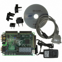
KIT STARTER SPARTAN-3
Manufacturer
Xilinx Inc
Series
Spartan-3r
Type
FPGA Configurationr
Datasheet
1.HW-SPAR3-SK-UNI-G.pdf
(64 pages)
Specifications of HW-SPAR3-SK-UNI-G
Contents
Board, Cable, Software, Datasheets and User Manual
For Use With/related Products
Spartan-3
Lead Free Status / RoHS Status
Lead free / RoHS Compliant
Other names
122-1521
Available stocks
Company
Part Number
Manufacturer
Quantity
Price


Power Distribution
AC Wall Adapter
Voltage Regulators
Table 12-1: Voltage Supplies and Sources
Spartan-3 FPGA Starter Kit Board User Guide
UG130 (v1.2) June 20, 2008
+5V DC
+3.3V DC
+2.5V DC
+1.2V DC
Voltage
AC Wall Adapter, 5V switching power supply
(
National Semiconductor LM1086CS-ADJ 3.3V
regulator (
STMicroelectronics LF25CDT 2.5V regulator
(
Fairchild Semiconductor FAN1112 1.2V
regulator (
28
25
R
in
in
Figure
Figure
The Spartan
produces a +5V DC output. Connect the AC wall adapter to the barrel connector along the
left edge of the board, indicated as
To disconnect power, remove the AC adapter from the wall or disconnect the barrel
connector.
The POWER indicator LED, shown as
applied to the board. If the jumpers in the J8 header and JP1 header are properly set and
there is a valid configuration data file in the Platform Flash memory, then the DONE
indicator LED, shown as
The AC wall adapter is directly compatible for North America, Japan, and Taiwan locales.
Other locations might require a socket adapter to convert from the North American
standard to the local power socket standard. The AC wall adapter operates from 100V to
240V AC input, at 50 or 60 Hz.
There are multiple voltages supplied on the Spartan-3 Starter Kit Board, as summarized in
Table
27
29
1-2)
1-2)
in
in
12-1.
Figure
Figure
Source
®
-3 FPGA Starter Kit includes an international-ready AC wall adapter that
1-2)
1-2)
www.xilinx.com
18
in
Figure
25
in
1-2, also lights up.
26
3.3V regulator
Optionally, PS/2 port via jumper JP2 setting
Pin 1 (VU) on A1, A2, B1 expansion connectors
2.5V and 1.2V regulators
V
Most components on the board
Pin 3 on A1, A2, B1 expansion connectors
V
V
Figure
CCO
CCAUX
CCINT
in
Figure
supply input for all FPGA I/O banks
supply input to FPGA
1-2. There is no power switch to the board.
supply input to FPGA
1-2, lights up when power is properly
Supplies
Chapter 12
45
Related parts for HW-SPAR3-SK-UNI-G
Image
Part Number
Description
Manufacturer
Datasheet
Request
R

Part Number:
Description:
STARTER KIT BUNDLE SPARTAN3/CPLD
Manufacturer:
Xilinx Inc
Part Number:
Description:
KIT HDWR FOR SPARTAN3/CPLD-JAPAN
Manufacturer:
Xilinx Inc

Part Number:
Description:
IC CPLD .8K 36MCELL 44-VQFP
Manufacturer:
Xilinx Inc
Datasheet:

Part Number:
Description:
IC CPLD 72MCRCELL 10NS 44VQFP
Manufacturer:
Xilinx Inc
Datasheet:

Part Number:
Description:
IC CPLD 1.6K 72MCELL 64-VQFP
Manufacturer:
Xilinx Inc
Datasheet:

Part Number:
Description:
IC CR-II CPLD 64MCELL 44-VQFP
Manufacturer:
Xilinx Inc
Datasheet:

Part Number:
Description:
IC CPLD 1.6K 72MCELL 100-TQFP
Manufacturer:
Xilinx Inc
Datasheet:

Part Number:
Description:
IC CR-II CPLD 64MCELL 56-BGA
Manufacturer:
Xilinx Inc
Datasheet:

Part Number:
Description:
IC CPLD 72MCRCELL 7.5NS 44VQFP
Manufacturer:
Xilinx Inc
Datasheet:
Part Number:
Description:
IC CR-II CPLD 64MCELL 100-VQFP
Manufacturer:
Xilinx Inc
Datasheet:
Part Number:
Description:
IC CPLD 1.6K 72MCELL 100-TQFP
Manufacturer:
Xilinx Inc
Datasheet:

Part Number:
Description:
IC CPLD 72MCRCELL 7.5NS 64VQFP
Manufacturer:
Xilinx Inc
Datasheet:
Part Number:
Description:
IC CPLD 1.6K 72MCELL 100-TQFP
Manufacturer:
Xilinx Inc
Datasheet:

Part Number:
Description:
IC CPLD 1.5K 64MCELL HP 44-VQFP
Manufacturer:
Xilinx Inc

Part Number:
Description:
IC CPLD 36MCRCELL 15NS 44PLCC
Manufacturer:
Xilinx Inc
Datasheet: