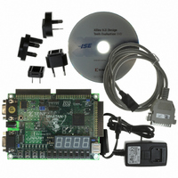
HW-SPAR3-SK-UNI-G Xilinx Inc, HW-SPAR3-SK-UNI-G Datasheet - Page 30

HW-SPAR3-SK-UNI-G
Manufacturer Part Number
HW-SPAR3-SK-UNI-G
Description
KIT STARTER SPARTAN-3
Manufacturer
Xilinx Inc
Series
Spartan-3r
Type
FPGA Configurationr
Datasheet
1.HW-SPAR3-SK-UNI-G.pdf
(64 pages)
Specifications of HW-SPAR3-SK-UNI-G
Contents
Board, Cable, Software, Datasheets and User Manual
For Use With/related Products
Spartan-3
Lead Free Status / RoHS Status
Lead free / RoHS Compliant
Other names
122-1521
Available stocks
Company
Part Number
Manufacturer
Quantity
Price
Mouse
30
Idle state
1
0
L
Start bit
R
R
Mouse status byte
0
1 XS YS XV YV P
The following site contains more information on PS/2 keyboard interfaces:
•
A mouse generates a clock and data signal when moved; otherwise, these signals remain
High indicating the Idle state. Each time the mouse is moved, the mouse sends three 11-bit
words to the host. Each of the 11-bit words contains a ‘0’ start bit, followed by 8 data bits
(LSB first), followed by an odd parity bit, and terminated with a ‘1’ stop bit. Each data
transmission contains 33 total bits, where bits 0, 11, and 22 are ‘0’ start bits, and bits 10, 21,
and 32 are ‘1’ stop bits. The three 8-bit data fields contain movement data as shown in
Figure
As shown in
moving the mouse to the right generates a positive value in the X field, and moving to the
left generates a negative value. Likewise, moving the mouse up generates a positive value
in the Y field, and moving down represents a negative value. The XS and YS bits in the
status byte define the sign of each value, where a ‘1’ indicates a negative value.
The magnitude of the X and Y values represent the rate of mouse movement. The larger the
value, the faster the mouse is moving. The XV and YV bits in the status byte indicate when
the X or Y values exceed their maximum value, an overflow condition. A ‘1’ indicates when
Figure 6-5: The Mouse Uses a Relative Coordinate System to Track Movement
The PS/2 Keyboard Interface
http://www.computer-engineering.org/index.php?title=PS/2_Keyboard_Interface
6-4. Data is valid at the falling edge of the clock, and the clock period is 20 to 30 kHz.
Stop bit
-X values
Figure 6-4: PS/2 Mouse Transaction
Figure
1
(XS=1)
Start bit
0
X0 X1 X2 X3 X4 X5 X6 X7 P
6-5, a PS/2 mouse employs a relative coordinate system wherein
X direction byte
www.xilinx.com
+Y values
-Y values
Stop bit
Spartan-3 FPGA Starter Kit Board User Guide
1
(YS=0)
(YS=1)
Chapter 6: PS/2 Mouse/Keyboard Port
Start bit
0
Y0 Y1 Y2 Y3 Y4 Y5 Y6 Y7 P
Y direction byte
UG130 (v1.2) June 20, 2008
UG130_c6_05_042404
+X values
(XS=0)
Stop bit
UG130_c6_04_042404
Idle state
1


