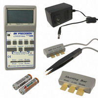
866 B&K Precision, 866 Datasheet - Page 20
Specifications of 866
Contents
Programmer, Adapter, Cable, Manual and Software
For Use With/related Products
EPROM, EEPROM-Flash, Serial EPROM, Microcontroller & PLD
Other names
866BK
Q2005647
Q2005647
Available stocks
Company
Part Number
Manufacturer
Quantity
Price
Part Number:
866590-0950
Manufacturer:
TOSHIBA/东芝
Quantity:
20 000
Company:
Part Number:
8669-001
Manufacturer:
TOSHIBA
Quantity:
6 222
Connecting 865 to the PC
Problems
interconnection, and their removing
Note: Due to low power consumption of 865 in inactive mode,
it doesn't require power switch. When the power LED indicator
glows with a low intensity, the 865 is in inactive mode.
Switch off PC and programmer. Insert the communication
cable included with your 865 programmer package to a free
printer port on your PC. If your computer is equipped with only
one printer port, substitute the programmer cable for the printer
cable. Connect the opposite cable end to the programmer.
Screw on both connectors to counter-connectors. This is very
important. It may be uncomfortable to switch between printer
cable and programmer cable, though it is not recommended to
operate the 865 programmer through a mechanical printer
switch. Use of an electronic printer switch is impossible. But
you can install a second multi-I/O in your computer, thus
obtaining a supplementary printer port, says LPT2. So your
printer may remain on LPT1 while the programmer on LPT2.
Switch on the PC.
Connect the mains connector of the power supply (or the wall-
plug power supply itself) to a mains plug, and then connect the
mini-DIN connector to the programmer's connector labeled
"12VAC". At this time all 'work result' LEDs (and 'POWER'
LED) light up successive and then switch off. Once the
POWER LED lights with low brightness then the 865
programmer is ready to run.
Next run the control program for 865.
Caution! If you don't want to switch off your PC when
connecting the 865, proceed as follows:
• When connecting the programmer to the PC: FIRST insert
• When disconnecting the programmer from the PC: FIRST
From 865's point of view the connecting and disconnecting
sequence is irrelevant. Protection circuits on all programmer
inputs keep it safe. But think of your PC please.
If you have any problems with 865
see section Common notes please.
the communications cable and THEN the power-supply
connector.
disconnect the power-supply connector and THEN the
communication cable.
related
20
to
the
PC interconnection,
865
PC


