866 B&K Precision, 866 Datasheet - Page 141
Specifications of 866
Contents
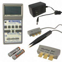
Programmer, Adapter, Cable, Manual and Software
For Use With/related Products
EPROM, EEPROM-Flash, Serial EPROM, Microcontroller & PLD
Other names
866BK
Q2005647
Q2005647
Available stocks
Company
Part Number
Manufacturer
Quantity
Price

Part Number:
866590-0950
Manufacturer:
TOSHIBA/东芝
Quantity:
20 000
Company:
Part Number:
8669-001
Manufacturer:
TOSHIBA
Quantity:
6 222


Programmer / Calibration test
Programmer / Create diagnostic report
Sequence for testing 6 pins ISP connector:
Sequence for testing 10 pins ISP connector:
We recommend run this test every 6 months.
Command executes test of programmer's calibration values.
Command Create Diagnostic report is used for writing more
particular
consequently copy Log window content to clipboard. The Log
window content can be placed from clipboard to any text
editor. Diagnostic report is useful when error occurs in control
program or programmer and kind of the error is, that user can
not resolve it oneself and he must contact programmer
manufacturer. In this case when customer send message to
HR1A 47R
HR1B 47R
HR1C 47R
1. Insert Diagnostic POD for ISP connectors into ZIF socket
2. Interconnect 6 pins connector of Diagnostic POD with an
3. Run selftest of ISP connector in PG4UW (Programmer /
1. Insert Diagnostic POD for ISP connectors into ZIF socket
2. Interconnect 10 pins connector of Diagnostic POD with
3. Run selftest of ISP connector in PG4UW (Programmer /
of the programmer. Diagnostic POD must be inserted as
40 pins device.
ISP connector of the programmer with an ISP cable,
included in programmer delivery package. Be sure that
pins are interconnected properly (i.e. 1-1, 2-2, ..., 6-6).
Selftest ISP connector).
of the programmer. Diagnostic POD must be inserted as
40 pins device.
an ISP connector of the programmer with an ISP cable,
included in delivery programmer package. Be sure that
pins are interconnected properly (i.e. 1-1, 2-2, ..., 10-10).
Selftest ISP connector).
ZIF7
ZIF4
ZIF9
ZIF1
ZIF2
ZIF3
ZIF5
ZIF4
diagnostic
1
3
6
2
4
5
J2
HARTING 09185106324
J3
HARTING 09185066324
information
1
3
5
7
9
1
3
5
141
10
2
4
6
8
2
4
6
ZIF3
ZIF5
ZIF6
ZIF8
ZIF11
ZIF6
ZIF8
ZIF2
to
ZIF1
ZIF2
ZIF3
ZIF4
ZIF5
ZIF6
ZIF7
ZIF8
ZIF9
ZIF11
Log
J1
DIP40 to ZIF socket
window
1
2
3
4
5
6
7
8
9
10
11
12
13
14
15
16
17
18
19
20 21
40
39
38
37
36
35
34
33
32
31
30
29
28
27
26
25
24
23
22
and
Related parts for 866
Image
Part Number
Description
Manufacturer
Datasheet
Request
R

Part Number:
Description:
B+K PRECISION 1690 REFURBISHED
Manufacturer:
B&K Precision
Datasheet:

Part Number:
Description:
B+K PRECISION 1786B CALIBRATED
Manufacturer:
B&K Precision
Part Number:
Description:
B+K PRECISION P/N 8540 CALIBRATED BY NEWARK SERVICES
Manufacturer:
B&K Precision

Part Number:
Description:
BK Precision Isolation Transformer, Isolation Leakage:
Manufacturer:
B&K Precision
Datasheet:
Part Number:
Description:
UNIVRSL PROGRAMMER W/INTERFACE
Manufacturer:
B&K Precision
Datasheet:
Part Number:
Description:
PROGRAMMER WIN/NT
Manufacturer:
B&K Precision
Datasheet:

Part Number:
Description:
Bench Top Power Supplies TRIPLE OUTPUT
Manufacturer:
B&K Precision
Datasheet:

Part Number:
Description:
Bench Top Power Supplies 0-30VDC 3 AMP
Manufacturer:
B&K Precision
Datasheet:

Part Number:
Description:
Bench Top Power Supplies 5000W PROGRAMMABLE DC ELECTRONIC LOAD
Manufacturer:
B&K Precision
Datasheet:

Part Number:
Description:
Bench Top Power Supplies QUAD DISPLAY TRIPLE OUTPUT 2-32V 1-5V 3A
Manufacturer:
B&K Precision
Datasheet:

Part Number:
Description:
Bench Top Power Supplies Power Supply/Battery
Manufacturer:
B&K Precision

Part Number:
Description:
Linear & Switching Power Supplies 1-36V 0-3A SWITCHING PS W/USB CHARGER
Manufacturer:
B&K Precision
Datasheet:

Part Number:
Description:
Function Generators & Synthesizers AUDIO GENERATOR
Manufacturer:
B&K Precision
Datasheet:

Part Number:
Description:
POWER SUPPLY, BENCH
Manufacturer:
B&K Precision
Datasheet:

Part Number:
Description:
AC Line Separator
Manufacturer:
B&K Precision
Datasheet: