866 B&K Precision, 866 Datasheet - Page 120
Specifications of 866
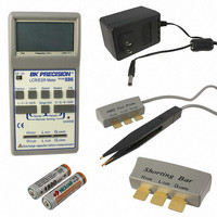
Contents
Programmer, Adapter, Cable, Manual and Software
For Use With/related Products
EPROM, EEPROM-Flash, Serial EPROM, Microcontroller & PLD
Other names
866BK
Q2005647
Q2005647
Available stocks
Company
Part Number
Manufacturer
Quantity
Price

Part Number:
866590-0950
Manufacturer:
TOSHIBA/东芝
Quantity:
20 000
Company:
Part Number:
8669-001
Manufacturer:
TOSHIBA
Quantity:
6 222


Ignore not programmed serial values means the not
programmed serial values are ignored and no action is done
with them.
Add not programmed serial values to file means the not
programmed serial values are added to file. The file of not
programmed serial values has the same text format as
serialization file for ”From-file” serialization mode. So there is
possible to program the serial values later on by ”From-file”
serialization mode.
If device programming is stopped by user, program will not
change the serial values ready for next batch of devices. The
same situation is if device program is incomplete, e.g. for
device insertion test error.
Ignoring or writing not programmed serial values is only used
when at least one device from current batch of devices in
multiple socket module programmer is completely programmed
and verified without errors.
Note: Serialization can work with control program’s main buffer
only. It means the serialization can be used for device areas
placed inside control program’s main buffer. Device special
areas placed outside the program’s main buffer could not use
serialization feature.
Device / Device options / Serialization /
Incremental mode
The Incremental mode enables to assign individual serial
numbers to each programmed device. A starting number
entered by user will be incremented by specified step for
each device program operation and loaded in selected
format to specified buffer address prior to programming of
each device.
There are following options, that user can modify for
incremental mode:
S / N size
S / N size option defines the number of bytes of serial value
which will be written to buffer. For Bin (binary) serialization
modes values 1-4 are valid for S / N size and for ASCII
serialization modes values 1-8 are valid for S / N size.
Address
Address option specifies the buffer address, where serial
value has to be written. Note that address range must be
inside the device start and device end addresses. Address
must be correctly specified so the last (highest or lowest)
byte of serial value must be inside device start and device
end address range.
120
Related parts for 866
Image
Part Number
Description
Manufacturer
Datasheet
Request
R

Part Number:
Description:
B+K PRECISION 1690 REFURBISHED
Manufacturer:
B&K Precision
Datasheet:

Part Number:
Description:
B+K PRECISION 1786B CALIBRATED
Manufacturer:
B&K Precision
Part Number:
Description:
B+K PRECISION P/N 8540 CALIBRATED BY NEWARK SERVICES
Manufacturer:
B&K Precision

Part Number:
Description:
BK Precision Isolation Transformer, Isolation Leakage:
Manufacturer:
B&K Precision
Datasheet:
Part Number:
Description:
UNIVRSL PROGRAMMER W/INTERFACE
Manufacturer:
B&K Precision
Datasheet:
Part Number:
Description:
PROGRAMMER WIN/NT
Manufacturer:
B&K Precision
Datasheet:

Part Number:
Description:
Bench Top Power Supplies TRIPLE OUTPUT
Manufacturer:
B&K Precision
Datasheet:

Part Number:
Description:
Bench Top Power Supplies 0-30VDC 3 AMP
Manufacturer:
B&K Precision
Datasheet:

Part Number:
Description:
Bench Top Power Supplies 5000W PROGRAMMABLE DC ELECTRONIC LOAD
Manufacturer:
B&K Precision
Datasheet:

Part Number:
Description:
Bench Top Power Supplies QUAD DISPLAY TRIPLE OUTPUT 2-32V 1-5V 3A
Manufacturer:
B&K Precision
Datasheet:

Part Number:
Description:
Bench Top Power Supplies Power Supply/Battery
Manufacturer:
B&K Precision

Part Number:
Description:
Linear & Switching Power Supplies 1-36V 0-3A SWITCHING PS W/USB CHARGER
Manufacturer:
B&K Precision
Datasheet:

Part Number:
Description:
Function Generators & Synthesizers AUDIO GENERATOR
Manufacturer:
B&K Precision
Datasheet:

Part Number:
Description:
POWER SUPPLY, BENCH
Manufacturer:
B&K Precision
Datasheet:

Part Number:
Description:
AC Line Separator
Manufacturer:
B&K Precision
Datasheet: