DO-CPLD-DK-G Xilinx Inc, DO-CPLD-DK-G Datasheet - Page 97
DO-CPLD-DK-G
Manufacturer Part Number
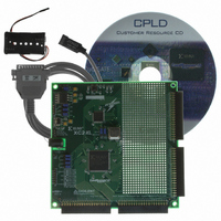
DO-CPLD-DK-G
Description
KIT DESIGN CPLD W/BATT HOLDER
Manufacturer
Xilinx Inc
Series
CoolRunner™- IIr
Type
CPLDr
Specifications of DO-CPLD-DK-G
Contents
Proto Board, Download Cable, Samples, Software
For Use With/related Products
CoolRunner-ll, XC9500XL
Lead Free Status / RoHS Status
Lead free / RoHS Compliant
Other names
122-1512
Available stocks
Company
Part Number
Manufacturer
Quantity
Price


Implementing CPLD Designs
Introduction
Synthesis
Programmable Logic Design
June 12, 2006
R
After you have successfully simulated your design, the synthesis stage converts the code-
based or schematic-based design into an NGC netlist file. The netlist is a non-readable file
that describes the actual circuit to be implemented at a very low level. The implementation
phase uses the netlist and a constraints file to recreate the design using the available
resources within the CPLD. Constraints may be physical or timing and are commonly used
for setting the required frequency of the design or declaring the required pinout.
The first step is Translate, also known as NGD Build because it is building an NGD file.
This step checks the design and ensures that the netlist is consistent with the chosen
architecture. Translate also checks the UCF for any inconsistencies. In effect, this stage
prepares the synthesized design for use within a CPLD.
The fit stage distributes the design to the resources in the CPLD and places those resources
according to the constraints specified. Obviously, if the design is too big for the chosen
device, the fit process will not be able to complete its job. The fitter uses the constraints that
were present in the UCF file to understand timing and may sometimes decide to change
the design to meet timing specifications. For example, sometimes the fitter will change the
D-Type flip-flops in the design to Toggle Type or T-Type registers. It all depends on how
well the design converts into product terms.
Note:
by the macrocells, switch matrix, and flip-flops are known, the chosen simulator can use information
for timing simulation.
The fitter creates a JEDEC file, which is used to program the device on the board either
using a parallel cable or programming equipment.
The steps of implementation must be carried out in this order. WebPACK ISE software will
automatically perform the steps required if a particular step is selected. For example, if the
design has only just been functionally simulated and you decide to do a timing simulation,
the software will automatically synthesize, translate, and fit the design. It will then
generate the timing information before it opens the simulator and gives the timing
simulation results.
The rest of this chapter demonstrates the steps required to successfully implement our
traffic light design.
The XST synthesis tool will only attempt to synthesize the file highlighted in the Sources
window. In our traffic light design, “top.vhd” (for VHDL designs) or “top_sch” (for
schematic designs) instantiates two lower level blocks, “stat_mac” and “counter.” The
Once the fitter has completed, it is good practice to re-simulate. As all the logic delays added
www.xilinx.com
Chapter 5
87
Related parts for DO-CPLD-DK-G
Image
Part Number
Description
Manufacturer
Datasheet
Request
R

Part Number:
Description:
STARTER KIT CPLD
Manufacturer:
Xilinx Inc
Datasheet:
Part Number:
Description:
KIT STARTER CPLD JAPANESE
Manufacturer:
Xilinx Inc
Datasheet:
Part Number:
Description:
KIT STARTER CPLD-JAPANESE
Manufacturer:
Xilinx Inc
Datasheet:

Part Number:
Description:
IC CPLD .8K 36MCELL 44-VQFP
Manufacturer:
Xilinx Inc
Datasheet:

Part Number:
Description:
IC CPLD 72MCRCELL 10NS 44VQFP
Manufacturer:
Xilinx Inc
Datasheet:

Part Number:
Description:
IC CPLD 1.6K 72MCELL 64-VQFP
Manufacturer:
Xilinx Inc
Datasheet:

Part Number:
Description:
IC CR-II CPLD 64MCELL 44-VQFP
Manufacturer:
Xilinx Inc
Datasheet:

Part Number:
Description:
IC CPLD 1.6K 72MCELL 100-TQFP
Manufacturer:
Xilinx Inc
Datasheet:

Part Number:
Description:
IC CR-II CPLD 64MCELL 56-BGA
Manufacturer:
Xilinx Inc
Datasheet:

Part Number:
Description:
IC CPLD 72MCRCELL 7.5NS 44VQFP
Manufacturer:
Xilinx Inc
Datasheet:
Part Number:
Description:
IC CR-II CPLD 64MCELL 100-VQFP
Manufacturer:
Xilinx Inc
Datasheet:
Part Number:
Description:
IC CPLD 1.6K 72MCELL 100-TQFP
Manufacturer:
Xilinx Inc
Datasheet:

Part Number:
Description:
IC CPLD 72MCRCELL 7.5NS 64VQFP
Manufacturer:
Xilinx Inc
Datasheet:
Part Number:
Description:
IC CPLD 1.6K 72MCELL 100-TQFP
Manufacturer:
Xilinx Inc
Datasheet:

Part Number:
Description:
IC CPLD 1.5K 64MCELL HP 44-VQFP
Manufacturer:
Xilinx Inc