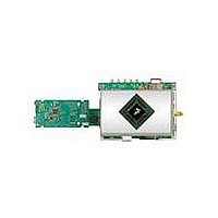
MCIMX35WPDKJ Freescale Semiconductor, MCIMX35WPDKJ Datasheet - Page 68

MCIMX35WPDKJ
Manufacturer Part Number
MCIMX35WPDKJ
Description
BOARD DEV FOR I.MX35
Manufacturer
Freescale Semiconductor
Series
i.MX35r
Type
MPUr
Datasheets
1.MCIMX35WPDKJ.pdf
(148 pages)
2.MCIMX35WPDKJ.pdf
(2 pages)
3.MCIMX35WPDKJ.pdf
(10 pages)
Specifications of MCIMX35WPDKJ
Contents
Module and Misc Hardware
Processor To Be Evaluated
i.MX35
Processor Series
i.MX35
Data Bus Width
32 bit
Interface Type
RS-232, Ethernet, USB, CAN, JTAG
Core
ARM11
For Use With/related Products
i.MX35
Lead Free Status / RoHS Status
Lead free / RoHS Compliant
- Current page: 68 of 148
- Download datasheet (3Mb)
The timing described in
different timing. The CSI can be programmed to support rising/falling-edge triggered SENSB_VSYNC;
active-high/low SENSB_HSYNC; and rising/falling-edge triggered SENSB_PIX_CLK.
4.9.12.3
Figure 47
4.9.13
This section describes the following types of display interfaces:
68
IP1
IP2
IP3
IP4
SENSB_DATA,
SENSB_VSYNC,
SENSB_HSYNC
ID
•
•
•
•
•
SENSB_PIX_CLK
(Sensor Output)
SENSB_MCLK
(Sensor Input)
Section 4.9.13.1, “Synchronous Interfaces”
Section 4.9.13.2, “Interface to Sharp HR-TFT Panels”
Section 4.9.13.3, “Synchronous Interface to Dual-Port Smart Displays”
Section 4.9.13.4, “Asynchronous Interfaces”
Section 4.9.13.5, “Serial Interfaces, Functional Description”
Sensor input clock frequency
Data and control setup time
Data and control holdup time
Sensor output (pixel) clock frequency
depicts the sensor interface timing, and
IPU
Electrical Characteristics
—
i.MX35 Applications Processors for Industrial and Consumer Products, Rev. 9
Display Interfaces
Figure 46
Table 51. Sensor Interface Timing Parameters
Parameter
Figure 47. Sensor Interface Timing Diagram
is that of a Motorola sensor. Some other sensors may have slightly
IP3
1/IP1
Table 51
IP2
lists the timing parameters.
Symbol
1/IP4
Fmck
Fpck
Tsu
Thd
Min.
0.01
0.01
5
3
Freescale Semiconductor
Max.
133
133
—
—
Units
MHz
MHz
ns
ns
Related parts for MCIMX35WPDKJ
Image
Part Number
Description
Manufacturer
Datasheet
Request
R
Part Number:
Description:
MCIMX-LVDS1
Manufacturer:
Freescale Semiconductor
Datasheet:
Part Number:
Description:
Manufacturer:
Freescale Semiconductor, Inc
Datasheet:
Part Number:
Description:
Manufacturer:
Freescale Semiconductor, Inc
Datasheet:
Part Number:
Description:
Manufacturer:
Freescale Semiconductor, Inc
Datasheet:
Part Number:
Description:
Manufacturer:
Freescale Semiconductor, Inc
Datasheet:
Part Number:
Description:
Manufacturer:
Freescale Semiconductor, Inc
Datasheet:
Part Number:
Description:
Manufacturer:
Freescale Semiconductor, Inc
Datasheet:
Part Number:
Description:
Manufacturer:
Freescale Semiconductor, Inc
Datasheet:
Part Number:
Description:
Manufacturer:
Freescale Semiconductor, Inc
Datasheet:
Part Number:
Description:
Manufacturer:
Freescale Semiconductor, Inc
Datasheet:
Part Number:
Description:
Manufacturer:
Freescale Semiconductor, Inc
Datasheet:
Part Number:
Description:
Manufacturer:
Freescale Semiconductor, Inc
Datasheet:
Part Number:
Description:
Manufacturer:
Freescale Semiconductor, Inc
Datasheet:
Part Number:
Description:
Manufacturer:
Freescale Semiconductor, Inc
Datasheet:
Part Number:
Description:
Manufacturer:
Freescale Semiconductor, Inc
Datasheet:


