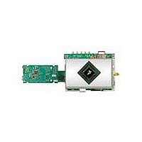
MCIMX35WPDKJ Freescale Semiconductor, MCIMX35WPDKJ Datasheet - Page 16

MCIMX35WPDKJ
Manufacturer Part Number
MCIMX35WPDKJ
Description
BOARD DEV FOR I.MX35
Manufacturer
Freescale Semiconductor
Series
i.MX35r
Type
MPUr
Datasheets
1.MCIMX35WPDKJ.pdf
(148 pages)
2.MCIMX35WPDKJ.pdf
(2 pages)
3.MCIMX35WPDKJ.pdf
(10 pages)
Specifications of MCIMX35WPDKJ
Contents
Module and Misc Hardware
Processor To Be Evaluated
i.MX35
Processor Series
i.MX35
Data Bus Width
32 bit
Interface Type
RS-232, Ethernet, USB, CAN, JTAG
Core
ARM11
For Use With/related Products
i.MX35
Lead Free Status / RoHS Status
Lead free / RoHS Compliant
- Current page: 16 of 148
- Download datasheet (3Mb)
4.3
This section provides power-up and power-down sequence guidelines for the i.MX35 processor.
4.3.1
The power-up sequence should be completed as follows:
16
Static
Note: Typical column: T
Power
Mode
1. Assert Power on Reset (POR).
2. Turn on digital logic domain and IO power supply: VDDn, NVCCx
3. Wait until VDDn and NVCCx power supplies are stable + 32 μs.
VDD1,2,3,4 = 1.1 V (min.)
ARM is in wait for interrupt mode.
MAX is halted
L2 cache is kept powered.
L2 cache control logic off.
AWB enabled.
MCU PLL is off.
PER PLL is off.
All clocks are gated off.
OSC 24MHz is on
OSC audio is off
RNGC internal osc is off
Supply Power-Up/Power-Down Requirements and Restrictions
Powering Up
Any i.MX35 board design must comply with the power-up and power-down
sequence guidelines as described in this section to guarantee reliable
operation of the device. Any deviation from these sequences can result in
irreversible damage to the i.MX35 processor (worst-case scenario).
Deviation from these sequences may also result in one or more of the
following:
•
•
•
i.MX35 Applications Processors for Industrial and Consumer Products, Rev. 9
Excessive current during power-up phase
Prevent the device from booting
Programming of unprogrammed fuses
A
Description
= 25 °C
Table 10. i.MX35 Power Modes (continued)
820
CAUTION
Typ.
QVCC (ARM/L2
NOTE
Peripheral)
µA
Max.
—
50
Typ.
MVDD/PVDD
µA
Max.
—
Freescale Semiconductor
OSC_AUDO_VDD
24
Typ.
OSC24M_VDD
µA
Max.
—
Related parts for MCIMX35WPDKJ
Image
Part Number
Description
Manufacturer
Datasheet
Request
R
Part Number:
Description:
MCIMX-LVDS1
Manufacturer:
Freescale Semiconductor
Datasheet:
Part Number:
Description:
Manufacturer:
Freescale Semiconductor, Inc
Datasheet:
Part Number:
Description:
Manufacturer:
Freescale Semiconductor, Inc
Datasheet:
Part Number:
Description:
Manufacturer:
Freescale Semiconductor, Inc
Datasheet:
Part Number:
Description:
Manufacturer:
Freescale Semiconductor, Inc
Datasheet:
Part Number:
Description:
Manufacturer:
Freescale Semiconductor, Inc
Datasheet:
Part Number:
Description:
Manufacturer:
Freescale Semiconductor, Inc
Datasheet:
Part Number:
Description:
Manufacturer:
Freescale Semiconductor, Inc
Datasheet:
Part Number:
Description:
Manufacturer:
Freescale Semiconductor, Inc
Datasheet:
Part Number:
Description:
Manufacturer:
Freescale Semiconductor, Inc
Datasheet:
Part Number:
Description:
Manufacturer:
Freescale Semiconductor, Inc
Datasheet:
Part Number:
Description:
Manufacturer:
Freescale Semiconductor, Inc
Datasheet:
Part Number:
Description:
Manufacturer:
Freescale Semiconductor, Inc
Datasheet:
Part Number:
Description:
Manufacturer:
Freescale Semiconductor, Inc
Datasheet:
Part Number:
Description:
Manufacturer:
Freescale Semiconductor, Inc
Datasheet:


