DM163035 Microchip Technology, DM163035 Datasheet - Page 92
DM163035
Manufacturer Part Number
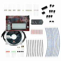
DM163035
Description
KIT DEVELOPMENT PICDEM LAB
Manufacturer
Microchip Technology
Type
MCUr
Datasheet
1.DM163035.pdf
(96 pages)
Specifications of DM163035
Contents
Board, Cable, Components, CD, PICkit Programmer
Processor To Be Evaluated
PIC10F, PIC12F615, PIC16F616
Data Bus Width
8 bit
Operating Supply Voltage
1.3 V to 5 V
Silicon Manufacturer
Microchip
Core Architecture
PIC
Core Sub-architecture
PIC10, PIC12, PIC16
Silicon Core Number
PIC10F, PIC12F, PIC16F
Silicon Family Name
PIC10F2xx, PIC12F6xx, PIC16F6xx
Lead Free Status / RoHS Status
Lead free / RoHS Compliant
For Use With/related Products
PIC10F206, PIC16F690, PIC16F819
Lead Free Status / Rohs Status
Lead free / RoHS Compliant


PICDEM
DS41369A-page 88
TM
EXAMPLE 5-9:
3. Copy/paste the code in Example 5-10 over the Get_Inputs() code from the
Lab Development Board User’s Guide
//Configure Port:
previous lab:
PORTB = 0;
//Disable pin output driver (See TRIS register)
TRISB4 = 1;
// Configure RB4 as analog pin as analog
ANS10 = 1;
//Configure RC0, RC1, RC2 and RC3 as digital output
PORTC = 0;
TRISC0 = 0;
ANS4 = 0;
//Configure Timer0 as follows:
//Select the FOSC/4 internal instruction clock
//as the clock source for TMR0
T0CS = 0;
//Increment TMR0 value on low-to-high transition
//of the FOSC/4
T0SE = 0;
//Assign the prescaler to TMR0
PSA = 1;
//Configure the prescaler to increment TMR0
//at a rate of 1:16
PS0 = 1;
PS1 = 1;
PS2 = 0;
//Configure the ADC module:
//Select ADC conversion clock Frc
ADCS0 = 1;
ADCS1 = 1;
ADCS2 = 1;
//Configure voltage reference using VDD
VCFG = 0;
//Select ADC input channel Pin 13 (RB4/AN10)
CHS0 = 0;
CHS1 = 1;
CHS2 = 0;
CHS3 = 1;
//Select result format left justified
ADFM = 0;
//Turn on ADC module
ADON = 1;
INITIALIZE CODE FOR ADC LAB 2
© 2009 Microchip Technology Inc.
Related parts for DM163035
Image
Part Number
Description
Manufacturer
Datasheet
Request
R

Part Number:
Description:
Manufacturer:
Microchip Technology Inc.
Datasheet:
Part Number:
Description:
Manufacturer:
Microchip Technology Inc.
Datasheet:
Part Number:
Description:
Manufacturer:
Microchip Technology Inc.
Datasheet:
Part Number:
Description:
Manufacturer:
Microchip Technology Inc.
Datasheet:
Part Number:
Description:
Manufacturer:
Microchip Technology Inc.
Datasheet:
Part Number:
Description:
Manufacturer:
Microchip Technology Inc.
Datasheet:
Part Number:
Description:
Manufacturer:
Microchip Technology Inc.
Datasheet:
Part Number:
Description:
Manufacturer:
Microchip Technology Inc.
Datasheet: