DM163035 Microchip Technology, DM163035 Datasheet - Page 91
DM163035
Manufacturer Part Number
DM163035
Description
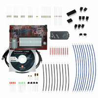
KIT DEVELOPMENT PICDEM LAB
Manufacturer
Microchip Technology
Type
MCUr
Datasheet
1.DM163035.pdf
(96 pages)
Specifications of DM163035
Contents
Board, Cable, Components, CD, PICkit Programmer
Processor To Be Evaluated
PIC10F, PIC12F615, PIC16F616
Data Bus Width
8 bit
Operating Supply Voltage
1.3 V to 5 V
Silicon Manufacturer
Microchip
Core Architecture
PIC
Core Sub-architecture
PIC10, PIC12, PIC16
Silicon Core Number
PIC10F, PIC12F, PIC16F
Silicon Family Name
PIC10F2xx, PIC12F6xx, PIC16F6xx
Lead Free Status / RoHS Status
Lead free / RoHS Compliant
For Use With/related Products
PIC10F206, PIC16F690, PIC16F819
Lead Free Status / Rohs Status
Lead free / RoHS Compliant


© 2009 Microchip Technology Inc.
Next, the Get_Inputs() performs an ADC on the voltage present on pin 13 using the
same code as Lab 1 with one minor change. This application is very dependant on the
timing of the software control loop. The 1mS delay used in Lab 1 to allow the hold
capacitor on the input of ADC to fully charge to the pin voltage is excessive. Using the
example given in Equation 9-1, Section 9 in the PIC16F690 Data Sheet as a reference,
the acquisition delay time is shortened to 8μS which should be sufficient.
The Decide() assigns the ADC result value, shifted three bit positions to the left, to
the TMR0_preload variable.
The Do_Outputs() assigns the current toggle bit value to RC0 that will transition
the output accordingly.
Finally, the Timing() clears the TMR0 overflow flag (T0IF), preloads the TMR0
register with the TMR0_preload value subtracted from 255. The function then waits
until the T0IF is set high before returning to the main(). In this way, as the temperature
at the thermistor increases, as will the frequency of the PWM.
5.2.4.2
Using the firmware developed in the previous lab, make the following changes:
1. Copy/paste the code in Example 5-8 into the top of the main firmware source file
EXAMPLE 5-8:
2. Copy/paste the code in Example 5-9 over the Initialize() code from the
Analog-to-Digital Converter Peripheral Labs
unsigned char LED_Output = 0; //assigned to PORTC to light
bit toggle = 0;//Used to generate waveform on RC0
unsigned char TMR0_preload = 0; //Varied by ADRESH to change
Note:
under the heading labeled:
//----------------DATA MEMORY---------------
previous lab:
PROCEDURE
Be sure to paste over the code from the previous lab.
GLOBAL VARIABLES USE IN ADC LAB 2
//waveform on RC0
//frequency of
//connected LEDs
DS41369A-page 87
Related parts for DM163035
Image
Part Number
Description
Manufacturer
Datasheet
Request
R

Part Number:
Description:
Manufacturer:
Microchip Technology Inc.
Datasheet:
Part Number:
Description:
Manufacturer:
Microchip Technology Inc.
Datasheet:
Part Number:
Description:
Manufacturer:
Microchip Technology Inc.
Datasheet:
Part Number:
Description:
Manufacturer:
Microchip Technology Inc.
Datasheet:
Part Number:
Description:
Manufacturer:
Microchip Technology Inc.
Datasheet:
Part Number:
Description:
Manufacturer:
Microchip Technology Inc.
Datasheet:
Part Number:
Description:
Manufacturer:
Microchip Technology Inc.
Datasheet:
Part Number:
Description:
Manufacturer:
Microchip Technology Inc.
Datasheet: