DM163035 Microchip Technology, DM163035 Datasheet - Page 12
DM163035
Manufacturer Part Number
DM163035
Description
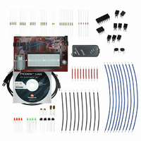
KIT DEVELOPMENT PICDEM LAB
Manufacturer
Microchip Technology
Type
MCUr
Datasheet
1.DM163035.pdf
(96 pages)
Specifications of DM163035
Contents
Board, Cable, Components, CD, PICkit Programmer
Processor To Be Evaluated
PIC10F, PIC12F615, PIC16F616
Data Bus Width
8 bit
Operating Supply Voltage
1.3 V to 5 V
Silicon Manufacturer
Microchip
Core Architecture
PIC
Core Sub-architecture
PIC10, PIC12, PIC16
Silicon Core Number
PIC10F, PIC12F, PIC16F
Silicon Family Name
PIC10F2xx, PIC12F6xx, PIC16F6xx
Lead Free Status / RoHS Status
Lead free / RoHS Compliant
For Use With/related Products
PIC10F206, PIC16F690, PIC16F819
Lead Free Status / Rohs Status
Lead free / RoHS Compliant


PICDEM
1.6
DS41369A-page 8
CONNECTING THE PICkit
TM
2. Using a 9V battery connected to connector BT1
3. A PICkit™ 2 Programmer/Debugger connected to any one of the three PICkit™
When using methods 1 or 2, each PIC
connect/disconnect jumper that, when in place, enables the positive supply voltage to
the respective V
troller sockets:
1. V
2. V
3. V
Using methods 1 or 2 enables the use of the variable V
supply voltages from approximately 1.3 to 5V. Rotating the potentiometer clockwise will
raise the supply voltage while rotating the potentiometer counterclockwise will
decrease the supply voltage.
The three PIC
PICkit™ Programmer/Debugger (ICSP™) connectors so that each can be pro-
grammed or debugged individually. The ICSP™ connect to the following PIC
controller sockets:
1. ICSP1 (J6) connects to the PIC
2. ICSP2 (J12) connects to the PIC
3. ICSP3 (J13) connects to the PIC
The PICkit™ Programmer/Debugger connects to the ICSP™ connector as shown in
Figure 1-2.
Lab Development Board User’s Guide
Note:
Ensure that connect/disconnect jumpers J14 are in place.
Programmer/Debugger connectors J13, J12 and J6 (recommended for
low-power applications only).
populating U2.
populating U3.
populating U5.
DD
DD
DD
1 (J3) connects/disconnects supply voltage to the PIC
2 (J4) connects/disconnects supply voltage to the PIC
3 (J5) connects/disconnects supply voltage to the PIC
When using the PICkit™ 2 Programmer/Debugger as the power source,
the variable V
®
microcontrollers populating sockets U5, U3 and U2 have their own
DD
pins. The V
™
2 PROGRAMMER/DEBUGGER
DD
potentiometer (R1) will not vary the supply voltage.
DD
jumpers connect to the following PIC
®
®
®
microcontroller populating U2.
®
microcontroller populating U3.
microcontroller populating U5.
microcontroller has an associated
DD
potentiometer (R1) to control
© 2009 Microchip Technology Inc.
®
®
®
microcontroller
microcontroller
microcontroller
®
microcon-
®
micro-
Related parts for DM163035
Image
Part Number
Description
Manufacturer
Datasheet
Request
R

Part Number:
Description:
Manufacturer:
Microchip Technology Inc.
Datasheet:
Part Number:
Description:
Manufacturer:
Microchip Technology Inc.
Datasheet:
Part Number:
Description:
Manufacturer:
Microchip Technology Inc.
Datasheet:
Part Number:
Description:
Manufacturer:
Microchip Technology Inc.
Datasheet:
Part Number:
Description:
Manufacturer:
Microchip Technology Inc.
Datasheet:
Part Number:
Description:
Manufacturer:
Microchip Technology Inc.
Datasheet:
Part Number:
Description:
Manufacturer:
Microchip Technology Inc.
Datasheet:
Part Number:
Description:
Manufacturer:
Microchip Technology Inc.
Datasheet: