DM163035 Microchip Technology, DM163035 Datasheet - Page 80
DM163035
Manufacturer Part Number
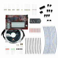
DM163035
Description
KIT DEVELOPMENT PICDEM LAB
Manufacturer
Microchip Technology
Type
MCUr
Datasheet
1.DM163035.pdf
(96 pages)
Specifications of DM163035
Contents
Board, Cable, Components, CD, PICkit Programmer
Processor To Be Evaluated
PIC10F, PIC12F615, PIC16F616
Data Bus Width
8 bit
Operating Supply Voltage
1.3 V to 5 V
Silicon Manufacturer
Microchip
Core Architecture
PIC
Core Sub-architecture
PIC10, PIC12, PIC16
Silicon Core Number
PIC10F, PIC12F, PIC16F
Silicon Family Name
PIC10F2xx, PIC12F6xx, PIC16F6xx
Lead Free Status / RoHS Status
Lead free / RoHS Compliant
For Use With/related Products
PIC10F206, PIC16F690, PIC16F819
Lead Free Status / Rohs Status
Lead free / RoHS Compliant


PICDEM
DS41369A-page 76
TM
5.2.3
5.2.3.1
To configure the peripherals used in this lab, the following registers are used:
1. ADC Control Register 0: ADCON0 (Register 9-1 in Section 9 of the PIC16F690
2. ADC Control Register 1: ADCON1 (Register 9-2 in Section 9 of the PIC16F690
3. ADC Result Register high: ADRESH (see Register 9-3 in Section 9 of the
4. ADC Result Register low: ADRESL (see Register 9-4 in Section 9 of the
5.2.3.2
In this lab, the ADC peripheral on the PIC16F690 is used to perform a simple
conversion of an analog voltage present on pin 13. The voltage is varied using a
100K
generate a 10-bit binary result via successive approximation stored into two 8-bit ADC
result registers ADRESH and ADRESL. The ADC result is software selectable as either
left or right justified as shown in Section 9.1.6 of the PIC16F690 Data Sheet. This
application will configure the ADC result as left justified with the four Most Significant
bits of the 10-bit result output to the RC0, RC1,RC2 and RC3 PORTC pins used to light
connected LEDs accordingly.The PICDEM™ Development Board configuration
schematic is shown in Figure 5-1.
Lab Development Board User’s Guide
- Configures ADC conversion result justification.
- Select ADC reference voltage.
- Selects ADC input channel (i.e., pin with analog voltage to be converted).
- Starts ADC conversion and determines when ADC conversion is complete.
- Enables the ADC peripheral.
- Determines ADC conversion clock.
- Holds upper 8-bits or upper 2-bits (depending on justification selected) of
- Holds lower 8-bits or lower 2-bit (depending on justification selected) of 10-bit
Data Sheet)
Data Sheet)
PIC16F690 Data Sheet)
10-bit ADC conversion result.
PIC16F690 Data Sheet)
ADC conversion result.
Ω
potentiometer. This voltage is compared against a reference voltage to
Lab 1: Simple ADC
NEW REGISTERS USED IN THIS LAB
OVERVIEW
© 2009 Microchip Technology Inc.
Related parts for DM163035
Image
Part Number
Description
Manufacturer
Datasheet
Request
R

Part Number:
Description:
Manufacturer:
Microchip Technology Inc.
Datasheet:
Part Number:
Description:
Manufacturer:
Microchip Technology Inc.
Datasheet:
Part Number:
Description:
Manufacturer:
Microchip Technology Inc.
Datasheet:
Part Number:
Description:
Manufacturer:
Microchip Technology Inc.
Datasheet:
Part Number:
Description:
Manufacturer:
Microchip Technology Inc.
Datasheet:
Part Number:
Description:
Manufacturer:
Microchip Technology Inc.
Datasheet:
Part Number:
Description:
Manufacturer:
Microchip Technology Inc.
Datasheet:
Part Number:
Description:
Manufacturer:
Microchip Technology Inc.
Datasheet: