DM163035 Microchip Technology, DM163035 Datasheet - Page 89
DM163035
Manufacturer Part Number
DM163035
Description
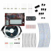
KIT DEVELOPMENT PICDEM LAB
Manufacturer
Microchip Technology
Type
MCUr
Datasheet
1.DM163035.pdf
(96 pages)
Specifications of DM163035
Contents
Board, Cable, Components, CD, PICkit Programmer
Processor To Be Evaluated
PIC10F, PIC12F615, PIC16F616
Data Bus Width
8 bit
Operating Supply Voltage
1.3 V to 5 V
Silicon Manufacturer
Microchip
Core Architecture
PIC
Core Sub-architecture
PIC10, PIC12, PIC16
Silicon Core Number
PIC10F, PIC12F, PIC16F
Silicon Family Name
PIC10F2xx, PIC12F6xx, PIC16F6xx
Lead Free Status / RoHS Status
Lead free / RoHS Compliant
For Use With/related Products
PIC10F206, PIC16F690, PIC16F819
Lead Free Status / Rohs Status
Lead free / RoHS Compliant


© 2009 Microchip Technology Inc.
5.2.4
5.2.4.1
In this lab, the ADC peripheral on the PIC16F690 is used to alter the frequency of
Pulse-Width Modulated Waveform (PWM) in relation to the temperature sensed by a
thermistor connected to the input of the ADC peripheral. The PWM waveform is gener-
ated by simply toggling the RC0 voltage level high and low. The thermistor is used to
create a voltage divider in conjunction with a 1KΩ resistor to vary the voltage into the
ADC input. This thermistor is a Negative Temperature Coefficient type (NTC) meaning
that as the temperature of the device increases, the resistance effectively decreases.
The voltage drop across the thermistor is converted by the ADC and the ADRESH
result then used to manipulate a TMR0 preload value (see GPIO Lab 3) that will be
used in the Timing() to vary the execution speed of the software control loop and ulti-
mately the frequency of the PWM waveform. The PWM will be connected to an
N-Channel MOSFET used to drive the 8Ω speaker on the PICDEM Lab Development
Board. The schematic for this lab is shown in Figure 5-5.
FIGURE 5-5:
Referring to the schematic in Figure 5-5, the RC0 connects to the gate of the IRFD010
N-Channel MOSFET Q1. Resistor R4 pulls the gate input low ensuring the transistor
will remain OFF until a high voltage level is present on the RC0 output. When the PWM
transitions high, Q1 is ON and current flows through the 8Ω speaker. The 100Ω R3
resistor is used to limit the current through the speaker to maintain manufacturer spec-
ified power ratings. In this way, any change in temperature around the thermistor will
alter the frequency of the PWM, thereby changing the audible frequency emitted from
the speaker.
Analog-to-Digital Converter Peripheral Labs
J8
Lab 2: Audible Temperature Sensor
OVERVIEW
Thermistor
10
1
2
3
4
5
6
7
8
9
SCHEMATIC FOR ADC LAB 2
V
RB4/AN10
U2
DD
V
R1
1KΩ
SS
RC0
R2
10KΩ
20
19
18
17
16
15
14
13
12
11
J9
V
R4
10KΩ
SS
V
DD
V
R3
100Ω
SS
Q1
IRFD010 N-Channel
MOSFET
SP+
SP-
J19
DS41369A-page 85
8Ω
LS1
Related parts for DM163035
Image
Part Number
Description
Manufacturer
Datasheet
Request
R

Part Number:
Description:
Manufacturer:
Microchip Technology Inc.
Datasheet:
Part Number:
Description:
Manufacturer:
Microchip Technology Inc.
Datasheet:
Part Number:
Description:
Manufacturer:
Microchip Technology Inc.
Datasheet:
Part Number:
Description:
Manufacturer:
Microchip Technology Inc.
Datasheet:
Part Number:
Description:
Manufacturer:
Microchip Technology Inc.
Datasheet:
Part Number:
Description:
Manufacturer:
Microchip Technology Inc.
Datasheet:
Part Number:
Description:
Manufacturer:
Microchip Technology Inc.
Datasheet:
Part Number:
Description:
Manufacturer:
Microchip Technology Inc.
Datasheet: