DM163035 Microchip Technology, DM163035 Datasheet - Page 44
DM163035
Manufacturer Part Number
DM163035
Description
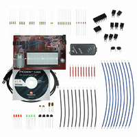
KIT DEVELOPMENT PICDEM LAB
Manufacturer
Microchip Technology
Type
MCUr
Datasheet
1.DM163035.pdf
(96 pages)
Specifications of DM163035
Contents
Board, Cable, Components, CD, PICkit Programmer
Processor To Be Evaluated
PIC10F, PIC12F615, PIC16F616
Data Bus Width
8 bit
Operating Supply Voltage
1.3 V to 5 V
Silicon Manufacturer
Microchip
Core Architecture
PIC
Core Sub-architecture
PIC10, PIC12, PIC16
Silicon Core Number
PIC10F, PIC12F, PIC16F
Silicon Family Name
PIC10F2xx, PIC12F6xx, PIC16F6xx
Lead Free Status / RoHS Status
Lead free / RoHS Compliant
For Use With/related Products
PIC10F206, PIC16F690, PIC16F819
Lead Free Status / Rohs Status
Lead free / RoHS Compliant


PICDEM
DS41369A-page 40
TM
of uncorrected switch bounce can range from being just annoying to catastrophic. The
classic solution involves filtering, such as through a resistor-capacitor circuit, or through
resettable shift registers. These methods are still effective but they involve additional
cost in material, installation and board real estate. Debouncing in software eliminates
these additional costs.
One of the simplest ways to switch debounce is to sample the switch until the signal is
stable or continue to sample the signal until no more bounces are detected. How long
to continue sampling requires some investigation. However, 5 mS is usually adequate,
while still reacting fast enough that the user won't notice it.
The software flowchart for this application is shown in Figure 3-19.
FIGURE 3-19:
The Initialize() now configures the following:
• PORTC
• PORTA
• Timer0 will be configured to implement the 5mS delay as follows:
• Initialize the LED_Output variable to ‘0’
• Initialize the direction bit variable to ‘0’
Lab Development Board User’s Guide
Global Variables:
• 8-bit variable LED_Output will be used to
• 1-bit variable direction used to deter-
- Configure PORTC pins as per the previous labs
- Clear PORTA register.
- Configure RA2 as a digital input pin
- Use the internal instruction clock F
- Increment TMR0 on the low-to-high transition of F
- Assign the prescaler to TMR0 and configure 1:64.
- This is a global variable that will be manipulated by the new Get_Inputs()
light the LEDs connected to PORTC
mine the direction of the sequential LED
flashing
0 = shift PORTC bits right-to-left
1 = shift PORTC bits left-to-right
(see Registers 4-1 and 4-2 in Section 4.1 of the PIC16F690 Data Sheet).
and used to determine PORTC shift direction by the Decide().
MAIN() SOFTWARE CONTROL LOOP FLOWCHART FOR
LAB 5
Loop Forever
OSC
/4 as the TMR0 clock source.
Initialize()
Do_Outputs()
Get_Inputs()
Decide()
Timing()
main()
OSC
/4.
© 2009 Microchip Technology Inc.
Related parts for DM163035
Image
Part Number
Description
Manufacturer
Datasheet
Request
R

Part Number:
Description:
Manufacturer:
Microchip Technology Inc.
Datasheet:
Part Number:
Description:
Manufacturer:
Microchip Technology Inc.
Datasheet:
Part Number:
Description:
Manufacturer:
Microchip Technology Inc.
Datasheet:
Part Number:
Description:
Manufacturer:
Microchip Technology Inc.
Datasheet:
Part Number:
Description:
Manufacturer:
Microchip Technology Inc.
Datasheet:
Part Number:
Description:
Manufacturer:
Microchip Technology Inc.
Datasheet:
Part Number:
Description:
Manufacturer:
Microchip Technology Inc.
Datasheet:
Part Number:
Description:
Manufacturer:
Microchip Technology Inc.
Datasheet: