DM300024 Microchip Technology, DM300024 Datasheet - Page 80
DM300024
Manufacturer Part Number
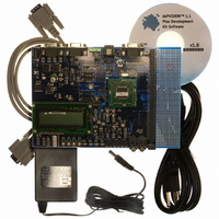
DM300024
Description
KIT DEMO DSPICDEM 1.1
Manufacturer
Microchip Technology
Type
MCUr
Specifications of DM300024
Contents
Board, Cable, CD, Power Supply
Silicon Manufacturer
Microchip
Core Architecture
DsPIC
Core Sub-architecture
DsPIC30F
Features
Serial Communication Channels Interface, General Purpose Prototyping Area
Silicon Core Number
DsPIC30F, DsPIC33F
Silicon Family Name
DsPIC30F6xxx, DsPIC33FJxxGPxxx
Rohs Compliant
Yes
Lead Free Status / RoHS Status
Lead free / RoHS Compliant
For Use With/related Products
dsPIC30F/33F and PIC24H
Lead Free Status / RoHS Status
Lead free / RoHS Compliant, Lead free / RoHS Compliant
Available stocks
Company
Part Number
Manufacturer
Quantity
Price
Company:

Part Number:
DM300024
Manufacturer:
MICROCHIP
Quantity:
12 000


dsPICDEM™ 1.1 Plus Development Board User’s Guide
B.3
DS70099D-page 76
COMMANDS
B.3.1
All commands recognized by the LCD controller are one to three bytes in length.
The command structure is designed to follow a simple rule that allows the interface to
be self-synchronizing at the command level (i.e., if a command is corrupted for some
reason, the controller can resynchronize on the command stream without special error
recovery procedures). The rule is that the first byte of a command always has its
MSB = 1 and the remaining bytes of the command have their MSB = 0. There is an
exception to the rule that MSB = 0 for all bytes except the first byte. Some of the column
commands can have data in the MSB of their second byte and thus, may violate this
rule. The processing code in the LCD controller will parse these special commands and
allow the command exception.
All commands follow the form of a leading identification byte followed by zero to three
data bytes. The data bytes are not condensed or combined with other data, or modified
from the native form of the data. There is no handshaking or flow control required
because of the speed and buffer depth of the controller. This greatly simplifies the
interface on the dsPIC DSC side since there is little advantage to putting wrappers
around the individual commands. Nothing needs to be done to the data other than to
send it.
B.3.2
The LCD has three data types, each based on its own independent coordinate
systems. The data types are:
• Character
• Pixel
• Column
Associated with each coordinate system is a “current” position of which each is
independent of the other. These positions are:
• CharPos
• PixPos
• ColPos
B.3.2.1
The character commands are used to write characters to the display. The character
coordinates are based on a 5 x 7 dot font justified to the upper left corner of the 6 x 8
box. The character cursor is a 5-pixel wide horizontal line that is justified to the lower
left corner of the 6 x 8 box and can be turned on or off, or can be set to blink.
Character operators are based on character coordinates R and C (i.e., Row and
Column). The current position, CharPos, specifies both the location of the character
cursor and the default position that the next character command will use. The home
position is the top left of the LCD display, ChrPos = (0,0).
The LCD accommodates four character rows (0-3) and 20 character columns (0-19).
Unless otherwise specified, incrementing ChrPosC beyond column 19 will wrap to the
next row (i.e., ChrPosC = 0 and ChrPosR + 1). If ChrPosR exceeds 3, it will wrap to
row 0.
Command Structure
Command Types
CHARACTERS
© 2006 Microchip Technology Inc.
Related parts for DM300024
Image
Part Number
Description
Manufacturer
Datasheet
Request
R

Part Number:
Description:
Manufacturer:
Microchip Technology Inc.
Datasheet:
Part Number:
Description:
Manufacturer:
Microchip Technology Inc.
Datasheet:
Part Number:
Description:
Manufacturer:
Microchip Technology Inc.
Datasheet:
Part Number:
Description:
Manufacturer:
Microchip Technology Inc.
Datasheet:
Part Number:
Description:
Manufacturer:
Microchip Technology Inc.
Datasheet:
Part Number:
Description:
Manufacturer:
Microchip Technology Inc.
Datasheet:
Part Number:
Description:
Manufacturer:
Microchip Technology Inc.
Datasheet:
Part Number:
Description:
Manufacturer:
Microchip Technology Inc.
Datasheet: