DM300024 Microchip Technology, DM300024 Datasheet - Page 63
DM300024
Manufacturer Part Number
DM300024
Description
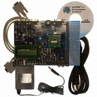
KIT DEMO DSPICDEM 1.1
Manufacturer
Microchip Technology
Type
MCUr
Specifications of DM300024
Contents
Board, Cable, CD, Power Supply
Silicon Manufacturer
Microchip
Core Architecture
DsPIC
Core Sub-architecture
DsPIC30F
Features
Serial Communication Channels Interface, General Purpose Prototyping Area
Silicon Core Number
DsPIC30F, DsPIC33F
Silicon Family Name
DsPIC30F6xxx, DsPIC33FJxxGPxxx
Rohs Compliant
Yes
Lead Free Status / RoHS Status
Lead free / RoHS Compliant
For Use With/related Products
dsPIC30F/33F and PIC24H
Lead Free Status / RoHS Status
Lead free / RoHS Compliant, Lead free / RoHS Compliant
Available stocks
Company
Part Number
Manufacturer
Quantity
Price
Company:

Part Number:
DM300024
Manufacturer:
MICROCHIP
Quantity:
12 000


4.8
© 2006 Microchip Technology Inc.
ADDITIONAL CODE EXAMPLES
The dsPICDEM™ 1.1 Plus Development Board Kit CD contains additional code
examples that exercise various features and peripherals of the dsPIC33F device:
CE111 – External Interrupt Pins:
Microchip's 16-bit dsPIC Digital Signal Controllers feature up to 5 external interrupt
pins: INT0 through INT4. These pins may be configured to interrupt on either a rising
or a falling edge of a signal.
This code example, written in C, demonstrates how the external interrupt pins can be
configured to interrupt the CPU. Both initialization and interrupt service routines have
been provided.
CE113 – Timer1 Used in Real-Time Clock Applications:
dsPIC Digital Signal Controllers feature several on-chip general purpose timers. Of
these, the Timer1 module has the capability to be clocked by an external asynchronous
32 kHz crystal connected to the device via the SOSCI and SOSCO pins. The attached
code example demonstrates how Timer1 may be configured to use the 32 kHz
secondary oscillator for a real-time clock (RTC) application.
Configuring Timer1 for the real-time clock application is a two step process. In the first
step, the code demonstrates how the secondary oscillator can be enabled via a special
write sequence to the OSCCON register. In the second step, the code demonstrates
how the Timer1 is configured to use an external asynchronous clock. In addition to
these steps, the code also demonstrates Timer1 interrupt operation.
CE114 – UART Loopback:
In this code examples, 256 byte transmit buffer is transmitted using UART and received
back in the receive buffer. This operation happens continuously.
CE121 – ADC Channel Scanning:
In this example, Timer 3 is set up to time-out every 125 microseconds (8 kHz rate). As
a result, the module stops sampling and triggers an A/D conversion on every Timer3
time-out (i.e., Ts=125µs).
ADC is configured in 10-bit mode to sequentially scan AIN0, AIN1, AIN2, AIN3, AIN4
and AIN5 on Timer 3 interrupt. It takes six Timer3 time-out periods to scan through all
the six analog inputs.
Using dsPIC33F and PIC24H/24F Devices
DS70099D-page 59
Related parts for DM300024
Image
Part Number
Description
Manufacturer
Datasheet
Request
R

Part Number:
Description:
Manufacturer:
Microchip Technology Inc.
Datasheet:
Part Number:
Description:
Manufacturer:
Microchip Technology Inc.
Datasheet:
Part Number:
Description:
Manufacturer:
Microchip Technology Inc.
Datasheet:
Part Number:
Description:
Manufacturer:
Microchip Technology Inc.
Datasheet:
Part Number:
Description:
Manufacturer:
Microchip Technology Inc.
Datasheet:
Part Number:
Description:
Manufacturer:
Microchip Technology Inc.
Datasheet:
Part Number:
Description:
Manufacturer:
Microchip Technology Inc.
Datasheet:
Part Number:
Description:
Manufacturer:
Microchip Technology Inc.
Datasheet: