DM300024 Microchip Technology, DM300024 Datasheet - Page 79
DM300024
Manufacturer Part Number
DM300024
Description
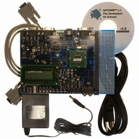
KIT DEMO DSPICDEM 1.1
Manufacturer
Microchip Technology
Type
MCUr
Specifications of DM300024
Contents
Board, Cable, CD, Power Supply
Silicon Manufacturer
Microchip
Core Architecture
DsPIC
Core Sub-architecture
DsPIC30F
Features
Serial Communication Channels Interface, General Purpose Prototyping Area
Silicon Core Number
DsPIC30F, DsPIC33F
Silicon Family Name
DsPIC30F6xxx, DsPIC33FJxxGPxxx
Rohs Compliant
Yes
Lead Free Status / RoHS Status
Lead free / RoHS Compliant
For Use With/related Products
dsPIC30F/33F and PIC24H
Lead Free Status / RoHS Status
Lead free / RoHS Compliant, Lead free / RoHS Compliant
Available stocks
Company
Part Number
Manufacturer
Quantity
Price
Company:

Part Number:
DM300024
Manufacturer:
MICROCHIP
Quantity:
12 000


B.1
B.2
© 2006 Microchip Technology Inc.
OVERVIEW
LCD CONTROLLER INTERFACE
Appendix B. LCD Controller Specification
The LCD display on the dsPICDEM™ 1.1 Plus Development Board is a PG12232D-L
8-bit 122 x 32 dot-matrix LCD controlled by a PIC18F242 LCD controller with a custom
driver that supports a rich set of character and graphic commands. The 122 x 32 LCD
supports a standard SED1520 type controller, which is interfaced to the PIC18F242
over a parallel interface bus. A full set of ASCII characters are available for display on a
4 x 20 character grid. In Graphics mode, individual pixels and bit patterns are
supported. A line drawing facility is supported as part of the basic command set.
The LCD controller (PIC18F242) is controlled via its Serial Peripheral Interface (SPI)
port. The LCD controller operates as a slave SPI with a maximum SPI clock of 2.4 MHz.
Using the standard PIC
under Slave Select (SS) control with CKP = 0 and CKE = 0.
The dsPIC DSC SPI peripheral should be configured for:
• SMP = 0
• CKE = 0
• CKP = 0
• MODE16 = 0 and MSTEN = 1
The SPI master clock should not exceed 2.4 MHz. The SS control line should be used
to synchronize the interface at the byte level.
On power-up, the LCD controller requires approximately 100 mS to initialize its internal
buffers and clear the LCD display. It will not accept any input until it has completed its
initialization sequence.
The controller stores incoming bytes in an interrupt buffer that is 186 bytes deep so that
the dsPIC DSC device should not be able, under reasonable operation, to overrun the
controller with input data. The buffer is large enough to hold a complete screen of
characters plus several additional commands. The only way to overrun the buffer is to
continuously send commands at a bit rate that is close to the maximum so that the LCD
controller is completely occupied with receiving and storing the incoming commands
and does not have sufficient extra time to process the commands. With SPI
communications, the dsPIC DSC device gets a return byte with every byte sent to the
controller. The controller provides the current buffer count as the return byte for each
byte sent. The return byte enables the dsPIC DSC device to determine how many
unprocessed bytes are in the controller’s buffer after the previous byte was received by
the controller. This number can never be less than the size of the proceeding command
sent since the controller will not remove a command from its receive buffer until the
entire command is received. This feature could be used for flow control by the dsPIC
DSC device, but given the speed of the controller and the size of the interrupt buffer, it
is unlikely the dsPIC DSC device could overflow the controller’s buffer under normal
usage. Thus, implementing flow control on the dsPIC DSC device in all but the most
unusual circumstances would be an unnecessary complication.
®
MCU nomenclature, the LCD controller is set up as a slave
DEVELOPMENT BOARD
dsPICDEM™ 1.1 PLUS
USER’S GUIDE
DS70099D-page 75
Related parts for DM300024
Image
Part Number
Description
Manufacturer
Datasheet
Request
R

Part Number:
Description:
Manufacturer:
Microchip Technology Inc.
Datasheet:
Part Number:
Description:
Manufacturer:
Microchip Technology Inc.
Datasheet:
Part Number:
Description:
Manufacturer:
Microchip Technology Inc.
Datasheet:
Part Number:
Description:
Manufacturer:
Microchip Technology Inc.
Datasheet:
Part Number:
Description:
Manufacturer:
Microchip Technology Inc.
Datasheet:
Part Number:
Description:
Manufacturer:
Microchip Technology Inc.
Datasheet:
Part Number:
Description:
Manufacturer:
Microchip Technology Inc.
Datasheet:
Part Number:
Description:
Manufacturer:
Microchip Technology Inc.
Datasheet: