DM300024 Microchip Technology, DM300024 Datasheet - Page 66
DM300024
Manufacturer Part Number
DM300024
Description
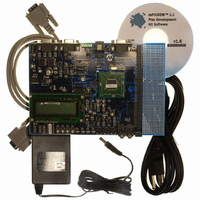
KIT DEMO DSPICDEM 1.1
Manufacturer
Microchip Technology
Type
MCUr
Specifications of DM300024
Contents
Board, Cable, CD, Power Supply
Silicon Manufacturer
Microchip
Core Architecture
DsPIC
Core Sub-architecture
DsPIC30F
Features
Serial Communication Channels Interface, General Purpose Prototyping Area
Silicon Core Number
DsPIC30F, DsPIC33F
Silicon Family Name
DsPIC30F6xxx, DsPIC33FJxxGPxxx
Rohs Compliant
Yes
Lead Free Status / RoHS Status
Lead free / RoHS Compliant
For Use With/related Products
dsPIC30F/33F and PIC24H
Lead Free Status / RoHS Status
Lead free / RoHS Compliant, Lead free / RoHS Compliant
Available stocks
Company
Part Number
Manufacturer
Quantity
Price
Company:

Part Number:
DM300024
Manufacturer:
MICROCHIP
Quantity:
12 000


dsPICDEM™ 1.1 Plus Development Board User’s Guide
DS70099D-page 62
FIGURE 5-2:
5.1.1
Two RS-232 serial communication channels are provided on the dsPICDEM™ 1.1 Plus
Development Board. One serial communication channel (DB9 connector J5/PORTB)
can be configured as an RS-232 or RS-485/RS-422 communication channel by setting
jumper J4 to the RX232/TX232 position. This jumper position connects the dsPIC DSC
UART channel 1 U1RX and U1TX pins to an RS-232 level-shifting IC (U3).
The serial port is configured as Data Communication Equipment (DCE), and can be
connected to a PC using a straight-through cable. If hardware handshaking is required,
inserting jumper J3 will connect CTS and RTS to port pins RD4 and RD5 on the dsPIC
DSC device. These pins can support CTS/RTS through a bit-bang control approach.
Both pins are connected to IC U3.
Setting jumper J4 to the TX485/RX485 position configures the dsPIC DSC UART
channel 1 U1RX and U1TX pins for a RS-485/RS-422 communication channel.
The second serial communication channel (DB9 connector J2/PORT A) is connected
to the dsPIC DSC UART channel 2 U2RX and U2TX pins via RS-232 level-shifting IC
(U1). This channel is a dedicated RS-232 serial communication channel. Hardware
flow control is not provided.
The schematic of these ports is shown in Figure A-5: “dsPICDEM™ 1.1 Plus Devel-
opment Board Schematic (Sheet 4 of 5)”
5.1.2
The CAN RXD and TXD lines of the SN65HVD230DR are connected to the dsPIC DSC
CANRX and CANTX pins. CAN bus signals (CANH and CANL) are available on DB9
connector J20. The CANH and CANL bus can be locally terminated with a 120 ohm
resistor by inserting jumper, J18.
The schematic of the CAN port is shown in Figure A-5: “dsPICDEM™ 1.1 Plus Devel-
opment Board Schematic (Sheet 4 of 5)”.
RS-232 Serial Ports
CAN Port
DEVICE PLUG-IN MODULE
Match the Pin 1 index marker of the
device to the lower left 45° corner of
the 80-pin QFP footprint (pin 1 of the
Emulation Header).
© 2006 Microchip Technology Inc.
Related parts for DM300024
Image
Part Number
Description
Manufacturer
Datasheet
Request
R

Part Number:
Description:
Manufacturer:
Microchip Technology Inc.
Datasheet:
Part Number:
Description:
Manufacturer:
Microchip Technology Inc.
Datasheet:
Part Number:
Description:
Manufacturer:
Microchip Technology Inc.
Datasheet:
Part Number:
Description:
Manufacturer:
Microchip Technology Inc.
Datasheet:
Part Number:
Description:
Manufacturer:
Microchip Technology Inc.
Datasheet:
Part Number:
Description:
Manufacturer:
Microchip Technology Inc.
Datasheet:
Part Number:
Description:
Manufacturer:
Microchip Technology Inc.
Datasheet:
Part Number:
Description:
Manufacturer:
Microchip Technology Inc.
Datasheet: