DM300024 Microchip Technology, DM300024 Datasheet - Page 69
DM300024
Manufacturer Part Number
DM300024
Description
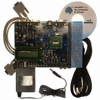
KIT DEMO DSPICDEM 1.1
Manufacturer
Microchip Technology
Type
MCUr
Specifications of DM300024
Contents
Board, Cable, CD, Power Supply
Silicon Manufacturer
Microchip
Core Architecture
DsPIC
Core Sub-architecture
DsPIC30F
Features
Serial Communication Channels Interface, General Purpose Prototyping Area
Silicon Core Number
DsPIC30F, DsPIC33F
Silicon Family Name
DsPIC30F6xxx, DsPIC33FJxxGPxxx
Rohs Compliant
Yes
Lead Free Status / RoHS Status
Lead free / RoHS Compliant
For Use With/related Products
dsPIC30F/33F and PIC24H
Lead Free Status / RoHS Status
Lead free / RoHS Compliant, Lead free / RoHS Compliant
Available stocks
Company
Part Number
Manufacturer
Quantity
Price
Company:

Part Number:
DM300024
Manufacturer:
MICROCHIP
Quantity:
12 000


© 2006 Microchip Technology Inc.
5.1.12
Headers J11 and J13-J15 provide a connection to the MPLAB ICE 4000 In-Circuit
Emulator. The emulation headers also support Plug-in Modules containing dsPIC30F,
dsPIC33F, PIC24H and PIC24F devices soldered onto adaptor boards (see
Section 5.1.18). These Plug-in Modules facilitate quick change out of the 80-pin TQFP
device.
The schematic of the Emulation Header is shown in Figure A-2: “dsPICDEM™ 1.1
Plus Development Board Schematic (Sheet 1 of 5)”.
5.1.13
The dsPICDEM™ 1.1 is powered by a +9V AC/DC wall adapter. Separate +3.3 V/+5V
DC regulators (V
prototyping area. Separate ground planes are connected through a single point.
Jumpers VDD_JMP and AVDD_JMP allow the supplied power source to be bypassed
and alternate supplies to be provided.
The schematics of the power supply circuits are shown in Figure A-3: “dsPICDEM™
1.1 Plus Development Board Schematic (Sheet 2 of 5)”.
5.1.14
A green LED is connected to the input of the regulators to indicate the presence of
power. See Figure A-3: “dsPICDEM™ 1.1 Plus Development Board Schematic
(Sheet 2 of 5)”.
5.1.15
• Crystal oscillator (7.3728 MHz) is supplied with the development board.
• Through holes and pads are provided for a user-furnished watch-type crystal and
• Socket and pads are provided for an output pull-up resistor for user furnished
• External clock connections from J1.
Jumpers J21 and J22 are used to select +3.3V or +5V operation. An incorrect jumper
setting can damage dsPIC30F/33F or PIC24H/24F Plug-In Modules. Configure for +5V
operation with dsPIC30F devices only. Configure for +3.3V operation for all other
devices.
two capacitors for SOSC1 and SOSC2.
oscillator to processor.
dsPICDEM™ 1.1 Development Hardware
Emulation Header
Power Supply
Power-on Indicator
Oscillator Options
DD
and AV
DD
) are provided to their respective processor pins and
CAUTION
DS70099D-page 65
Related parts for DM300024
Image
Part Number
Description
Manufacturer
Datasheet
Request
R

Part Number:
Description:
Manufacturer:
Microchip Technology Inc.
Datasheet:
Part Number:
Description:
Manufacturer:
Microchip Technology Inc.
Datasheet:
Part Number:
Description:
Manufacturer:
Microchip Technology Inc.
Datasheet:
Part Number:
Description:
Manufacturer:
Microchip Technology Inc.
Datasheet:
Part Number:
Description:
Manufacturer:
Microchip Technology Inc.
Datasheet:
Part Number:
Description:
Manufacturer:
Microchip Technology Inc.
Datasheet:
Part Number:
Description:
Manufacturer:
Microchip Technology Inc.
Datasheet:
Part Number:
Description:
Manufacturer:
Microchip Technology Inc.
Datasheet: