DM300024 Microchip Technology, DM300024 Datasheet - Page 41
DM300024
Manufacturer Part Number
DM300024
Description
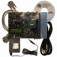
KIT DEMO DSPICDEM 1.1
Manufacturer
Microchip Technology
Type
MCUr
Specifications of DM300024
Contents
Board, Cable, CD, Power Supply
Silicon Manufacturer
Microchip
Core Architecture
DsPIC
Core Sub-architecture
DsPIC30F
Features
Serial Communication Channels Interface, General Purpose Prototyping Area
Silicon Core Number
DsPIC30F, DsPIC33F
Silicon Family Name
DsPIC30F6xxx, DsPIC33FJxxGPxxx
Rohs Compliant
Yes
Lead Free Status / RoHS Status
Lead free / RoHS Compliant
For Use With/related Products
dsPIC30F/33F and PIC24H
Lead Free Status / RoHS Status
Lead free / RoHS Compliant, Lead free / RoHS Compliant
Available stocks
Company
Part Number
Manufacturer
Quantity
Price
Company:

Part Number:
DM300024
Manufacturer:
MICROCHIP
Quantity:
12 000


© 2006 Microchip Technology Inc.
dsPIC30F Demonstration Program Operation
3.4.2
The step-by-step Main Loop execution sequence is shown in Table 3-4.
TABLE 3-4:
Seq
10
1
2
3
4
5
6
7
8
9
Main Loop Code Execution
12-bit ADC collects 256 samples from the digital potentiometer output on AN3 into
a RAM buffer. It also collects one sample each from AN4 (RP2), AN5 (RP3), AN6
(RP1) and AN8 (Temperature Sensor U9). All A/D conversions are performed in
an interrupt-driven configuration.
Buffered data set is filtered using an IIR filter to remove line noise. The filter can
be changed to an FIR filter or no filter from the DSP menu options. The filtering
operation is benchmarked using the Timer4/5 pair.
A complex in-place 256-point FFT is performed on the filtered data set, resulting
in complex frequency data (x + jy). This operation is benchmarked using the
Timer4/5 pair.
Squared magnitude is computed for each frequency bin in an in-place fashion
(x
The magnitude data is run through a routine that returns the frequency bin and
magnitude of the largest element.
The magnitude of the largest element is compared against a threshold and
captured if it is greater than the threshold so that low-level noise does not show
up as a frequency estimate. (Provides a simplified peak-detection algorithm.)
If a Timer3 count has expired, a software flag is set to inform the CPU that the
results recorded may now be displayed. This ensures that the CPU refreshes the
display buffers.
Any user choices entered via the switches SW1-SW4 are checked and the new
user selections are applied. May involve a change of display screen or some
parameter displayed on the LCD.
The changes are communicated to the PIC18F242 LCD controller via the SPI 2
module.
In the special case of the DTMF menu, the main routine may also kick off the DCI
module operation when the user requests DTMF tone generation.
2
+ y
MAIN LOOP CODE EXECUTION SEQUENCE
2
).
Program Task
DS70099D-page 37
Related parts for DM300024
Image
Part Number
Description
Manufacturer
Datasheet
Request
R

Part Number:
Description:
Manufacturer:
Microchip Technology Inc.
Datasheet:
Part Number:
Description:
Manufacturer:
Microchip Technology Inc.
Datasheet:
Part Number:
Description:
Manufacturer:
Microchip Technology Inc.
Datasheet:
Part Number:
Description:
Manufacturer:
Microchip Technology Inc.
Datasheet:
Part Number:
Description:
Manufacturer:
Microchip Technology Inc.
Datasheet:
Part Number:
Description:
Manufacturer:
Microchip Technology Inc.
Datasheet:
Part Number:
Description:
Manufacturer:
Microchip Technology Inc.
Datasheet:
Part Number:
Description:
Manufacturer:
Microchip Technology Inc.
Datasheet: