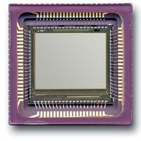
CYII5SC1300-EVAL Cypress Semiconductor Corp, CYII5SC1300-EVAL Datasheet - Page 20

CYII5SC1300-EVAL
Manufacturer Part Number
CYII5SC1300-EVAL
Description
BOARD EVAL IMG SENS IBIS5-B-1300
Manufacturer
Cypress Semiconductor Corp
Specifications of CYII5SC1300-EVAL
Sensor Type
CMOS Imaging, Color (RGB)
Sensing Range
1.3 Megapixel
Interface
Parallel/Serial
Sensitivity
106 fps
Voltage - Supply
3 V ~ 4.5 V
Embedded
No
Utilized Ic / Part
IBIS5-B-1300
Lead Free Status / RoHS Status
Contains lead / RoHS non-compliant
Lead Free Status / RoHS Status
Lead free / RoHS Compliant, Contains lead / RoHS non-compliant
Document #: 38-05710 Rev. *A
Rolling Shutter Operation
The integration of the light in the image sensor is done during
readout of the other lines.
The only difference with synchronous shutter is that the
TIME_OUT pin is used to indicate when the Y_SYNC pulse for
the right Y-shift-register (reset Y-shift register) is generated.
This loads the right Y-shift-register with the pointer loaded in
register YR_REG. The Y_SYNC pulse for the left Y-shift
register (read Y-shift register) is generated with Y_START.
The INT_TIME register defines how many lines have to be
counted before the Y_SYNC of the right Y-shift-register is
generated, hence defining the integration time. See also
“INT_TIME Register (11:0)” on page 14
description of the rolling shutter operation.
T
register(INT_TIME)
Note For normal operation the values of the YL_REG and
YR_REG registers are equal.
int
Integration time [# lines] = register(NROF_LINES) –
Figure 26. Windowing in the X-direction
Figure 25. Rolling Shutter Operation
for a detailed
Windowing in X-direction
An X_LOAD pulse overrides the internal X_SYNC signal,
loading a new X-pointer (stored in the X_REG register) into the
X-shift-register.
The X_LOAD pulse has to appear on the falling edge of
SYS_CLOCK and has to remain 2 SYS_CLOCK cycles high
overlapping 2 rising edges of SYS_CLOCK. On one of the 2
rising edges of SYS_CLOCK the new X-pointer is loaded.
T
from the previous register load to the rising edge of X_LOAD.
It depends on the settling time of the register and the
X-decoder.
The actual time to load the register itself depends on the
interface mode that is used.
The parallel interface is the fastest.
Table 19.T
Parallel interface
Serial 3 Wire
load
Interface mode
is the available time to upload the register and is defined
load
for Different Interfaces
T
load
16
1
(µs)
(about 40 SYS_CLOCK cycles)
(at 2.5 MHz data rate)
CYII5FM1300AB
IBIS5-B-1300
Page 20 of 42
[+] Feedback


