CYII5SC1300-EVAL Cypress Semiconductor Corp, CYII5SC1300-EVAL Datasheet - Page 17
CYII5SC1300-EVAL
Manufacturer Part Number
CYII5SC1300-EVAL
Description
BOARD EVAL IMG SENS IBIS5-B-1300
Manufacturer
Cypress Semiconductor Corp
Specifications of CYII5SC1300-EVAL
Sensor Type
CMOS Imaging, Color (RGB)
Sensing Range
1.3 Megapixel
Interface
Parallel/Serial
Sensitivity
106 fps
Voltage - Supply
3 V ~ 4.5 V
Embedded
No
Utilized Ic / Part
IBIS5-B-1300
Lead Free Status / RoHS Status
Contains lead / RoHS non-compliant
Lead Free Status / RoHS Status
Lead free / RoHS Compliant, Contains lead / RoHS non-compliant


Document #: 38-05710 Rev. *A
Figure 19. Recommended Schematic for Generating
Basic Signals
Figure 20. Relative Timing of the 5 Sequencer Control Signal
Timing Diagrams
Timing Requirements
There are 6 control signals that operate the image sensor:
These control signals must be generated by the external
system with following time constraints to SYS_CLOCK (rising
edge = active edge):
T
T
It is important that these signals are free of any glitches.
Figure 19
the basic signals and to avoid any timing problems.
Figure 21. Synchronous Shutter: Single Slope Integration
SYS_CLOCK_N
• SS_START
• SS_STOP
• Y_CLOCK
• Y_START
• X_LOAD
• SYS_CLOCK
SETUP
HOLD
> 7.5 ns
>7.5 ns
shows a recommended schematic for generating
FF
SS_START
SS_STOP
Y_CLOCK
Y_START
X_LOAD
SYS_CLOCK
Synchronous Shutter: Single Slope Integration
SS_START and SS_STOP must change on the falling edge of
the SYS_CLOCK (Tsetup and Thold > 7.5 ns). The pulse width
of both signals must be a minimum of 1 SYS_CLOCK cycle.
As long as SS_START or SS_STOP are asserted, the
sequencer stays in a suspended state. (See
T
INT_TIME register is reached. The integration timer is clocked
by the granulated SS-sequencer clock.
T
SS-sequencer clock period.
T
the TIME_OUT signal to trigger the SS_STOP pin (or use an
external counter to trigger SS_STOP); both signals cannot be
tied together.
T
signals to reset the image core and start integration. This takes
4 granulated SS-sequencer clock periods. The integration
time counter starts counting at the first rising edge after the
falling edge of SS_START.
T
state. It takes 2 granulated SS-sequencer clock periods.
T
1
2
3
4
5
int
—Time counted by the integration timer until the value of
—TIME_OUT
—There are no constraints for this time. The user can use
—During this time, the SS-sequencer applies the control
—The SS-sequencer puts the image core in a readable
—The “real” integration or exposure time.
signal
stays
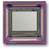
CYII5FM1300AB
high
IBIS5-B-1300
for
Figure
Page 17 of 42
1
granulated
21.)
[+] Feedback
Related parts for CYII5SC1300-EVAL
Image
Part Number
Description
Manufacturer
Datasheet
Request
R

Part Number:
Description:
Manufacturer:
Cypress Semiconductor Corp
Datasheet:
Part Number:
Description:
Manufacturer:
Cypress Semiconductor Corp
Datasheet:
Part Number:
Description:
Manufacturer:
Cypress Semiconductor Corp
Datasheet:
Part Number:
Description:
Manufacturer:
Cypress Semiconductor Corp
Datasheet:
Part Number:
Description:
Manufacturer:
Cypress Semiconductor Corp
Datasheet: