STEVAL-IFS012V1 STMicroelectronics, STEVAL-IFS012V1 Datasheet - Page 37
STEVAL-IFS012V1
Manufacturer Part Number
STEVAL-IFS012V1
Description
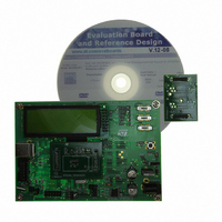
BOARD ST72651AR6/STTS75/STLM20
Manufacturer
STMicroelectronics
Specifications of STEVAL-IFS012V1
Sensor Type
Temperature
Sensing Range
Depends on IC
Interface
I²C, USB
Sensitivity
Depends on IC
Voltage - Supply
5V
Embedded
Yes, MCU, 8-Bit
Utilized Ic / Part
ST72F651AR6, STTS75, STLM20
Lead Free Status / RoHS Status
Lead free / RoHS Compliant
Other names
497-8419
Available stocks
Company
Part Number
Manufacturer
Quantity
Price


7 INTERRUPTS
7.1 INTRODUCTION
The CPU enhanced interrupt management pro-
vides the following features:
■
■
■
This interrupt management is based on:
– Bit 5 and bit 3 of the CPU CC register (I1:0),
– Interrupt software priority registers (ISPRx),
– Fixed interrupt vector addresses located at the
This enhanced interrupt controller guarantees full
upward compatibility with the standard (not nest-
ed) CPU interrupt controller.
7.2 MASKING AND PROCESSING FLOW
The interrupt masking is managed by the I1 and I0
bits of the CC register and the ISPRx registers
which give the interrupt software priority level of
each interrupt vector (see
ing flow is shown in
Figure 25. Interrupt Processing Flowchart
high addresses of the memory map (FFE0h to
FFFFh) sorted by hardware priority order.
– Up to 4 software programmable nesting levels
– Up to 16 interrupt vectors fixed by hardware
– 3 non maskable events: RESET, TRAP, TLI
Hardware interrupts
Software interrupt (TRAP)
Nested or concurrent interrupt management
with
management:
flexible
RESTORE PC, X, A, CC
FROM STACK
RESET
interrupt
Figure
Table
25.
priority
8). The process-
Y
and
INSTRUCTION
INTERRUPT
INSTRUCTION
FETCH NEXT
PENDING
EXECUTE
N
“IRET”
N
Doc ID 7215 Rev 4
level
Y
When an interrupt request has to be serviced:
– Normal processing is suspended at the end of
– The PC, X, A and CC registers are saved onto
– I1 and I0 bits of CC register are set according to
– The PC is then loaded with the interrupt vector of
The interrupt service routine should end with the
IRET instruction which causes the contents of the
saved registers to be recovered from the stack.
Note: As a consequence of the IRET instruction,
the I1 and I0 bits will be restored from the stack
and the program in the previous level will resume.
Table 8. Interrupt Software Priority Levels
Level 0 (main)
Level 1
Level 2
Level 3 (= interrupt disable)
Interrupt software priority
the current instruction execution.
the stack.
the corresponding values in the ISPRx registers
of the serviced interrupt vector.
the interrupt to service and the first instruction of
the interrupt service routine is fetched (refer to
“Interrupt Mapping” table for vector addresses).
STAYS PENDING
THE INTERRUPT
Interrupt has the same or a
LOAD I1:0 FROM INTERRUPT SW REG.
LOAD PC FROM INTERRUPT VECTOR
lower software priority
than current one
STACK PC, X, A, CC
Level
High
Low
I1:0
TLI
ST72651AR6
N
I1
0
0
1
1
Y
37/161
I0
1
0
1
0
1
Related parts for STEVAL-IFS012V1
Image
Part Number
Description
Manufacturer
Datasheet
Request
R

Part Number:
Description:
BOARD EVAL SPZB260 MOD FOR STR9
Manufacturer:
STMicroelectronics
Datasheet:

Part Number:
Description:
BOARD EVAL EXTENSION SN250
Manufacturer:
STMicroelectronics
Datasheet:

Part Number:
Description:
BOARD EVAL AB-54003L-512
Manufacturer:
STMicroelectronics
Datasheet:

Part Number:
Description:
BOARD REF DESIGN RF DMOS PWR AMP
Manufacturer:
STMicroelectronics
Datasheet:

Part Number:
Description:
BOARD EVAL PWR AMP AB-84008L-470
Manufacturer:
STMicroelectronics
Datasheet:

Part Number:
Description:
BOARD EVAL FOR STM32F103XX
Manufacturer:
STMicroelectronics
Datasheet:

Part Number:
Description:
BOARD EVAL AB-54003L-512
Manufacturer:
STMicroelectronics
Datasheet:

Part Number:
Description:
BOARD SMART PLUG STM32 SPZB260PR
Manufacturer:
STMicroelectronics
Datasheet:

Part Number:
Description:
BOARD DEMO BLUETOOTH SPBT2532C2
Manufacturer:
STMicroelectronics
Datasheet:
Part Number:
Description:
ZIGBEE USB DONGLE EVAL KIT
Manufacturer:
STMicroelectronics
Datasheet:
Part Number:
Description:
STMicroelectronics [RIPPLE-CARRY BINARY COUNTER/DIVIDERS]
Manufacturer:
STMicroelectronics
Datasheet:
Part Number:
Description:
STMicroelectronics [LIQUID-CRYSTAL DISPLAY DRIVERS]
Manufacturer:
STMicroelectronics
Datasheet:

Part Number:
Description:
BOARD EVAL FOR MEMS SENSORS
Manufacturer:
STMicroelectronics
Datasheet: