STEVAL-IFS012V1 STMicroelectronics, STEVAL-IFS012V1 Datasheet - Page 35
STEVAL-IFS012V1
Manufacturer Part Number
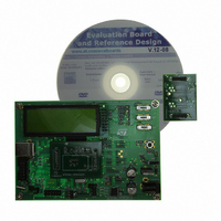
STEVAL-IFS012V1
Description
BOARD ST72651AR6/STTS75/STLM20
Manufacturer
STMicroelectronics
Specifications of STEVAL-IFS012V1
Sensor Type
Temperature
Sensing Range
Depends on IC
Interface
I²C, USB
Sensitivity
Depends on IC
Voltage - Supply
5V
Embedded
Yes, MCU, 8-Bit
Utilized Ic / Part
ST72F651AR6, STTS75, STLM20
Lead Free Status / RoHS Status
Lead free / RoHS Compliant
Other names
497-8419
Available stocks
Company
Part Number
Manufacturer
Quantity
Price


POWER SUPPLY MANAGEMENT (Cont’d)
6.4.3 Storage Media Interface I/Os
The microcontroller is able to drive Storage Media
through an interface operating at a different volt-
age from the rest of the circuit.
This is achieved by powering the Storage Media
interface I/O circuitry through a specific supply rail
connected to V
either as an input or output.
If the on-chip voltage regulator is off, power to the
interface I/Os should be provided externally to the
V
Alone Mode, or in USB mode when the current re-
quired to power the Storage Media is above the
current capacity of the on-chip regulator.
If the on-chip voltage regulator is on, it powers the
interface I/Os, and V
age Media. This is recommended in USB Mode,
when the current required to power the Storage
Media is within the capacity of the on-chip regula-
tor.
Caution: If VDDF is supplied externally, the regu-
lator must not be enabled.
Important Note:
If V
be used and are tied to ground. Refer to
9.2.4
Application Example:
Stand-Alone Mode
– The Storage Media interface supply is powered
DDF
by V
nects V
any True Open Drain I/O pin and controlled by
user software.
DDF
for more details.
pin. This should be the case when in Stand-
DD
is not present, all V
enabled by an external switch which con-
DD
to V
DDF
DDF
pin. The V
. This switch can be driven by
DDF
pin can supply the Stor-
DDF
DDF
-driven I/Os cannot
pin can be used
Section
Doc ID 7215 Rev 4
– The on-chip voltage regulator must be disabled
USB Mode
– In this case the core of the microcontroller is run-
– The Storage Media Interface can be powered
– The regulator output voltage can be pro-
– Should the current requirement for the Storage
Caution: The user should ensure that V
not exceed the maximum rating specified for the
Storage Media V
AGE switch on.
to avoid any conflict and to decrease consump-
tion (reset the REGEN bit in the PCR register).
ning from the USB bus power or the self power
supply. V
a voltage from 4.0 to 5.5V.
through the on-chip regulator (providing power to
the I/O pins and output on pin V
requirement is within the output capacity of the
on chip regulator.
grammed to 2.8V, 3.3V, 3.4V or 3.5 Volts, de-
pending on the Storage Media specifications.
(see VSET[1:0] bits in PCR register description)
Media be higher than the current capacity of the
on chip regulator, an external regulator should be
used. Thus the on-chip voltage regulator must be
disabled to avoid any conflict (reset the REGEN
bit in the PCR register).
DD
and USBV
DDF
max when switching STOR-
DD
pins are supplied with
DDF
ST72651AR6
) if the current
DD
35/161
does
1
Related parts for STEVAL-IFS012V1
Image
Part Number
Description
Manufacturer
Datasheet
Request
R

Part Number:
Description:
BOARD EVAL SPZB260 MOD FOR STR9
Manufacturer:
STMicroelectronics
Datasheet:

Part Number:
Description:
BOARD EVAL EXTENSION SN250
Manufacturer:
STMicroelectronics
Datasheet:

Part Number:
Description:
BOARD EVAL AB-54003L-512
Manufacturer:
STMicroelectronics
Datasheet:

Part Number:
Description:
BOARD REF DESIGN RF DMOS PWR AMP
Manufacturer:
STMicroelectronics
Datasheet:

Part Number:
Description:
BOARD EVAL PWR AMP AB-84008L-470
Manufacturer:
STMicroelectronics
Datasheet:

Part Number:
Description:
BOARD EVAL FOR STM32F103XX
Manufacturer:
STMicroelectronics
Datasheet:

Part Number:
Description:
BOARD EVAL AB-54003L-512
Manufacturer:
STMicroelectronics
Datasheet:

Part Number:
Description:
BOARD SMART PLUG STM32 SPZB260PR
Manufacturer:
STMicroelectronics
Datasheet:

Part Number:
Description:
BOARD DEMO BLUETOOTH SPBT2532C2
Manufacturer:
STMicroelectronics
Datasheet:
Part Number:
Description:
ZIGBEE USB DONGLE EVAL KIT
Manufacturer:
STMicroelectronics
Datasheet:
Part Number:
Description:
STMicroelectronics [RIPPLE-CARRY BINARY COUNTER/DIVIDERS]
Manufacturer:
STMicroelectronics
Datasheet:
Part Number:
Description:
STMicroelectronics [LIQUID-CRYSTAL DISPLAY DRIVERS]
Manufacturer:
STMicroelectronics
Datasheet:

Part Number:
Description:
BOARD EVAL FOR MEMS SENSORS
Manufacturer:
STMicroelectronics
Datasheet: