STEVAL-IFS012V1 STMicroelectronics, STEVAL-IFS012V1 Datasheet - Page 21
STEVAL-IFS012V1
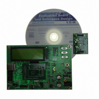
Manufacturer Part Number
STEVAL-IFS012V1
Description
BOARD ST72651AR6/STTS75/STLM20
Manufacturer
STMicroelectronics
Specifications of STEVAL-IFS012V1
Sensor Type
Temperature
Sensing Range
Depends on IC
Interface
I²C, USB
Sensitivity
Depends on IC
Voltage - Supply
5V
Embedded
Yes, MCU, 8-Bit
Utilized Ic / Part
ST72F651AR6, STTS75, STLM20
Lead Free Status / RoHS Status
Lead free / RoHS Compliant
Other names
497-8419
Available stocks
Company
Part Number
Manufacturer
Quantity
Price


FLASH PROGRAM MEMORY (Cont’d)
4.5 ICC Interface
ICC needs a minimum of 4 and up to 6 pins to be
connected to the programming tool (see
12). These pins are:
Figure 12. Typical ICC Interface
Notes:
1. If the ICCCLK or ICCDATA pins are only used
as outputs in the application, no signal isolation is
necessary. As soon as the Programming Tool is
plugged to the board, even if an ICC session is not
in progress, the ICCCLK and ICCDATA pins are
not available for the application. If they are used as
inputs by the application, isolation such as a serial
resistor has to implemented in case another de-
vice forces the signal. Refer to the Programming
Tool documentation for recommended resistor val-
ues.
2. During the ICC session, the programming tool
must control the RESET pin. This can lead to con-
flicts between the programming tool and the appli-
cation reset circuit if it drives more than 5mA at
high level (push pull output or pull-up resistor<1K).
A schottky diode can be used to isolate the appli-
cation RESET circuit in this case. When using a
classical RC network with R>1K or a reset man-
– RESET: device reset
– V
APPLICATION
POWER SUPPLY
SS
: device power supply ground
(See Note 3)
PROGRAMMING TOOL
C
L2
OPTIONAL
(See Note 4)
C
ST7
L1
Figure
Doc ID 7215 Rev 4
10kΩ
10
ICC CONNECTOR
9
agement IC with open drain output and pull-up re-
sistor>1K, no additional components are needed.
In all cases the user must ensure that no external
reset is generated by the application during the
ICC session.
3. The use of Pin 7 of the ICC connector depends
on the Programming Tool architecture. This pin
must be connected when using most ST Program-
ming Tools (it is used to monitor the application
power supply). Please refer to the Programming
Tool manual.
4. Pin 9 has to be connected to the OSC1 or OS-
CIN pin of the ST7 when the clock is not available
in the application or if the selected clock option is
not programmed in the option byte. ST7 devices
with multioscillator capability need to have OSC2
grounded in this case.
7
8
– ICCCLK: ICC output serial clock pin
– ICCDATA: ICC input/output serial data pin
– ICCSEL/V
– OSC1(or OSCIN): main clock input for exter-
– V
nal source (optional)
ure
5
6
DD
ICC Cable
12, Note 3)
: application board power supply (see
4
3
1
2
PP
HE10 CONNECTOR TYPE
: programming voltage
ICC CONNECTOR
APPLICATION BOARD
APPLICATION
See Note 2
APPLICATION
RESET SOURCE
See Note 1
I/O
ST72651AR6
21/161
Fig-
1
Related parts for STEVAL-IFS012V1
Image
Part Number
Description
Manufacturer
Datasheet
Request
R

Part Number:
Description:
BOARD EVAL SPZB260 MOD FOR STR9
Manufacturer:
STMicroelectronics
Datasheet:

Part Number:
Description:
BOARD EVAL EXTENSION SN250
Manufacturer:
STMicroelectronics
Datasheet:

Part Number:
Description:
BOARD EVAL AB-54003L-512
Manufacturer:
STMicroelectronics
Datasheet:

Part Number:
Description:
BOARD REF DESIGN RF DMOS PWR AMP
Manufacturer:
STMicroelectronics
Datasheet:

Part Number:
Description:
BOARD EVAL PWR AMP AB-84008L-470
Manufacturer:
STMicroelectronics
Datasheet:

Part Number:
Description:
BOARD EVAL FOR STM32F103XX
Manufacturer:
STMicroelectronics
Datasheet:

Part Number:
Description:
BOARD EVAL AB-54003L-512
Manufacturer:
STMicroelectronics
Datasheet:

Part Number:
Description:
BOARD SMART PLUG STM32 SPZB260PR
Manufacturer:
STMicroelectronics
Datasheet:

Part Number:
Description:
BOARD DEMO BLUETOOTH SPBT2532C2
Manufacturer:
STMicroelectronics
Datasheet:
Part Number:
Description:
ZIGBEE USB DONGLE EVAL KIT
Manufacturer:
STMicroelectronics
Datasheet:
Part Number:
Description:
STMicroelectronics [RIPPLE-CARRY BINARY COUNTER/DIVIDERS]
Manufacturer:
STMicroelectronics
Datasheet:
Part Number:
Description:
STMicroelectronics [LIQUID-CRYSTAL DISPLAY DRIVERS]
Manufacturer:
STMicroelectronics
Datasheet:

Part Number:
Description:
BOARD EVAL FOR MEMS SENSORS
Manufacturer:
STMicroelectronics
Datasheet: