STEVAL-IFS006V1 STMicroelectronics, STEVAL-IFS006V1 Datasheet - Page 72
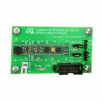
STEVAL-IFS006V1
Manufacturer Part Number
STEVAL-IFS006V1
Description
BOARD EVAL 8BIT MICRO + TDE1708
Manufacturer
STMicroelectronics
Datasheets
1.TDE1708DFT.pdf
(14 pages)
2.STEVAL-IFS006V1.pdf
(136 pages)
3.STEVAL-IFS006V1.pdf
(4 pages)
Specifications of STEVAL-IFS006V1
Design Resources
STEVAL-IFS006V1 Bill of Material
Sensor Type
Proximity
Interface
I²C
Voltage - Supply
6 V ~ 48 V
Embedded
Yes, MCU, 8-Bit
Utilized Ic / Part
ST7FLITEUS5, TDE1708
Processor To Be Evaluated
ST7LITEUS5
Data Bus Width
8 bit
Operating Supply Voltage
6 V to 48 V
Silicon Manufacturer
ST Micro
Silicon Core Number
TDE1708DFT
Kit Application Type
Sensing - Touch / Proximity
Application Sub Type
Proximity Switch
Kit Contents
Board
Rohs Compliant
Yes
Lead Free Status / RoHS Status
Lead free / RoHS Compliant
Sensitivity
-
Sensing Range
-
Lead Free Status / Rohs Status
Lead free / RoHS Compliant
Other names
497-6403
STEVAL-IFS006V1
STEVAL-IFS006V1
Available stocks
Company
Part Number
Manufacturer
Quantity
Price


On-chip peripherals
Note:
Note:
Caution:
72/136
PWM frequency and duty cycle
The PWM signal frequency (f
value.
f
Following the above formula, if f
register value = 4094), and the minimum value is 2 kHz (ATR register value = 0).
The maximum value of ATR is 4094 because it must be lower than the DCR value which
must be 4095 in this case.
At reset, the counter starts counting from 0.
Software must write the duty cycle value in the DCR0H and DCR0L preload registers. The
DCR0H register must be written first. See caution below.
When a upcounter overflow occurs (OVF event), the ATR value is loaded in the upcounter,
the preloaded Duty cycle value is transferred to the Duty Cycle register and the PWM0
signal is set to a high level. When the upcounter matches the DCRx value the PWM0 signals
is set to a low level. To obtain a signal on the PWM0 pin, the contents of the DCR0 register
must be greater than the contents of the ATR register.
The polarity bit can be used to invert the output signal.
The maximum available resolution for the PWM0 duty cycle is:
Resolution = 1 / (4096 - ATR)
To get the maximum resolution (1/4096), the ATR register must be 0. With this maximum
resolution and assuming that DCR=ATR, a 0% or 100% duty cycle can be obtained by
changing the polarity.
As soon as the DCR0H is written, the compare function is disabled and will start only when
the DCR0L value is written. If the DCR0H write occurs just before the compare event, the
signal on the PWM output may not be set to a low level. In this case, the DCRx register
should be updated just after an OVF event. If the DCR and ATR values are close, then the
DCRx register should be updated just before an OVF event, in order not to miss a compare
event and to have the right signal applied on the PWM output.
Figure 34. PWM function
PWM
= f
COUNTER
AUTO-RELOAD
DUTY CYCLE
WITH OE0=1
AND OP0=0
WITH OE0=1
AND OP0=1
REGISTER
REGISTER
(DCR0)
(ATR)
4095
000
/ (4096 - ATR)
PWM
CPU
) is controlled by the counter period and the ATR register
is 8 MHz, the maximum value of f
ST7LITEUS2, ST7LITEUS5
PWM
is 4 MHz (ATR
t
Related parts for STEVAL-IFS006V1
Image
Part Number
Description
Manufacturer
Datasheet
Request
R

Part Number:
Description:
BOARD EVAL SPZB260 MOD FOR STR9
Manufacturer:
STMicroelectronics
Datasheet:

Part Number:
Description:
BOARD EVAL EXTENSION SN250
Manufacturer:
STMicroelectronics
Datasheet:

Part Number:
Description:
BOARD EVAL AB-54003L-512
Manufacturer:
STMicroelectronics
Datasheet:

Part Number:
Description:
BOARD REF DESIGN RF DMOS PWR AMP
Manufacturer:
STMicroelectronics
Datasheet:

Part Number:
Description:
BOARD EVAL PWR AMP AB-84008L-470
Manufacturer:
STMicroelectronics
Datasheet:

Part Number:
Description:
BOARD EVAL FOR STM32F103XX
Manufacturer:
STMicroelectronics
Datasheet:

Part Number:
Description:
BOARD EVAL AB-54003L-512
Manufacturer:
STMicroelectronics
Datasheet:

Part Number:
Description:
BOARD SMART PLUG STM32 SPZB260PR
Manufacturer:
STMicroelectronics
Datasheet:

Part Number:
Description:
BOARD DEMO BLUETOOTH SPBT2532C2
Manufacturer:
STMicroelectronics
Datasheet:
Part Number:
Description:
ZIGBEE USB DONGLE EVAL KIT
Manufacturer:
STMicroelectronics
Datasheet:
Part Number:
Description:
STMicroelectronics [RIPPLE-CARRY BINARY COUNTER/DIVIDERS]
Manufacturer:
STMicroelectronics
Datasheet:
Part Number:
Description:
STMicroelectronics [LIQUID-CRYSTAL DISPLAY DRIVERS]
Manufacturer:
STMicroelectronics
Datasheet:

Part Number:
Description:
BOARD EVAL FOR MEMS SENSORS
Manufacturer:
STMicroelectronics
Datasheet: