NCP1351LEDGEVB ON Semiconductor, NCP1351LEDGEVB Datasheet - Page 10
NCP1351LEDGEVB
Manufacturer Part Number
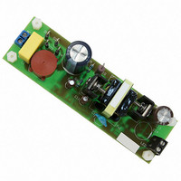
NCP1351LEDGEVB
Description
EVAL BOARD FOR NCP1351LEDG
Manufacturer
ON Semiconductor
Datasheets
1.NCP1351APG.pdf
(27 pages)
2.NCP1351LEDGEVB.pdf
(11 pages)
3.NCP1351LEDGEVB.pdf
(3 pages)
Specifications of NCP1351LEDGEVB
Design Resources
NCP1351 EVB BOM NCP1351LEDGEVB Gerber Files NCP1351LED EVB Schematic
Current - Output / Channel
700mA
Outputs And Type
1, Isolated
Voltage - Output
33V
Features
Short-Circuit Protection
Voltage - Input
85 ~ 265 V
Utilized Ic / Part
NCP1351
Core Chip
NCP1351
Topology
Flyback
No. Of Outputs
1
Output Current
700mA
Output Voltage
33V
Development Tool Type
Hardware - Eval/Demo Board
Leaded Process Compatible
Yes
Rohs Compliant
Yes
Lead Free Status / RoHS Status
Lead free / RoHS Compliant
For Use With/related Products
NCP1351LEDG
Other names
NCP1351LEDGEVBOS


The Negative Sensing Technique
sensing technique as portrayed by Figure 6. In this
technique, the controller detects a positive voltage drop
across the sense resistor, representative of the flowing
current. Unfortunately, this solution suffers from the
following drawbacks:
In this simplified example, the source directly connects to
the controller ground. Hence, if V
gate-source voltage is very close to 8 V: no sense resistor
drop. How does the controller detect a negative excursion?
In lack of primary current, the voltage on the CS pin reaches
R
1 V on this pin. Now, when the power MOSFET activates,
the current flows via the sense resistor and develop a
negative voltage by respect to the controller ground. The
voltage seen on the CS is nothing else than a positive voltage
(R
is negative. Thus, the CS pin voltage goes low as the primary
offset
Standard current-mode controllers use the positive
Figure 7 represents the negative current sense technique.
offset
Figure 6. Positive Current-Sense Technique
1. Difficulties to precisely adjust the peak current. If
2. The voltage developed across the sense resistor
3. The current in the sense resistor also includes the
+
C
x I
I
1 V is the maximum sense level, you must
combine low valued resistors to reach the exact
limit you need.
subtracts from the gate voltage. If your VCC
is 7 V, then the actual gate voltage at the end of the
on time, assuming a full load condition, is 7 V –
1 V = 6 V.
C
disturbs the controller and requires adequate
treatment through a LEB circuitry for instance.
x I
Bulk
Lp
iss
CS
CS
. Let us assume that these elements lead to have
current at turn-on. This narrow spike often
) plus the voltage across the sense resistor which
Reset
I
Lp
I
Lp
+
-
Peak
Setpoint
DRV
CS
CC
R
GND
is 8 V, the effective
sense
V
gs
L
P
APPLICATION INFORMATION
I
Lp
V
sense
http://onsemi.com
(min)
NCP1351
10
current increases. When the result reaches the threshold
voltage (around 20 mV), the comparator toggles and resets
the main latch. Figure 3 details how the voltage moves on the
CS pin on a 1351 demoboard, whereas Figure 9 zooms on
the sense resistor voltage captured by respect to the
controller ground.
want to develop 1 V across the sense resistor. You would
select the offset resistor via the following formula:
ohm law to obtain the sense resistor value:
to a 0.33 W resistor. In that case, the peak current will exceed
the 2 A limit. Why not changing the offset resistor value
then? To obtain 2 A from the 0.33 W resistor, you should
develop:
The offset resistor is thus derived by:
V sense + R sense I peak_max + 0.33
improve the efficiency, we recommend to adopt sense values
between 0.5 V and 1 V. Reducing the voltage below these
levels will degrade the noise immunity.
V
+
C
Figure 7. A Simplified Circuit of the Negative Sense
The choice of these two elements is simple. Suppose you
If you need a peak current of 2 A, then, simply apply the
Due to the circuit flexibility, suppose you only have access
If reducing the sense resistor is of good practice to
I
offset
Bulk
Lp
R offset +
R sense +
R offset +
CS
V
R
sense
offset
V
DD
ICS
I CS
0.66
I CS
I peak_max
+
1
V
Implementation
th
+
+
-
+
1
270 m
270 m
0.66
1
+
Reset
+ 3.7 kW
+ 2.44 kW
I
1
2
Lp
+ 0.5 W
DRV
GND
2 + 660 mV
L
P
I
Lp
(eq. 1)
(eq. 2)
(eq. 3)
(eq. 4)
Related parts for NCP1351LEDGEVB
Image
Part Number
Description
Manufacturer
Datasheet
Request
R

Part Number:
Description:
ON Semiconductor [VOLTAGE REGULATOR]
Manufacturer:
ON Semiconductor
Datasheet:
Part Number:
Description:
357-036-542-201 CARDEDGE 36POS DL .156 BLK LOPRO
Manufacturer:
ON Semiconductor
Datasheet:
Part Number:
Description:
357-036-542-201 CARDEDGE 36POS DL .156 BLK LOPRO
Manufacturer:
ON Semiconductor
Datasheet:
Part Number:
Description:
357-036-542-201 CARDEDGE 36POS DL .156 BLK LOPRO
Manufacturer:
ON Semiconductor
Datasheet:
Part Number:
Description:
357-036-542-201 CARDEDGE 36POS DL .156 BLK LOPRO
Manufacturer:
ON Semiconductor
Datasheet:
Part Number:
Description:
357-036-542-201 CARDEDGE 36POS DL .156 BLK LOPRO
Manufacturer:
ON Semiconductor
Datasheet:
Part Number:
Description:
357-036-542-201 CARDEDGE 36POS DL .156 BLK LOPRO
Manufacturer:
ON Semiconductor
Datasheet:
Part Number:
Description:
357-036-542-201 CARDEDGE 36POS DL .156 BLK LOPRO
Manufacturer:
ON Semiconductor
Datasheet:
Part Number:
Description:
357-036-542-201 CARDEDGE 36POS DL .156 BLK LOPRO
Manufacturer:
ON Semiconductor
Datasheet:
Part Number:
Description:
357-036-542-201 CARDEDGE 36POS DL .156 BLK LOPRO
Manufacturer:
ON Semiconductor
Datasheet:
Part Number:
Description:
357-036-542-201 CARDEDGE 36POS DL .156 BLK LOPRO
Manufacturer:
ON Semiconductor
Datasheet:
Part Number:
Description:
Manufacturer:
ON Semiconductor
Datasheet:
Part Number:
Description:
Manufacturer:
ON Semiconductor
Datasheet:
Part Number:
Description:
Manufacturer:
ON Semiconductor
Datasheet: