NCP1351LEDGEVB ON Semiconductor, NCP1351LEDGEVB Datasheet
NCP1351LEDGEVB
Manufacturer Part Number
NCP1351LEDGEVB
Description
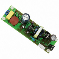
EVAL BOARD FOR NCP1351LEDG
Manufacturer
ON Semiconductor
Datasheets
1.NCP1351APG.pdf
(27 pages)
2.NCP1351LEDGEVB.pdf
(11 pages)
3.NCP1351LEDGEVB.pdf
(3 pages)
Specifications of NCP1351LEDGEVB
Design Resources
NCP1351 EVB BOM NCP1351LEDGEVB Gerber Files NCP1351LED EVB Schematic
Current - Output / Channel
700mA
Outputs And Type
1, Isolated
Voltage - Output
33V
Features
Short-Circuit Protection
Voltage - Input
85 ~ 265 V
Utilized Ic / Part
NCP1351
Core Chip
NCP1351
Topology
Flyback
No. Of Outputs
1
Output Current
700mA
Output Voltage
33V
Development Tool Type
Hardware - Eval/Demo Board
Leaded Process Compatible
Yes
Rohs Compliant
Yes
Lead Free Status / RoHS Status
Lead free / RoHS Compliant
For Use With/related Products
NCP1351LEDG
Other names
NCP1351LEDGEVBOS


Introduction:
The NCP1351 LED Driver Board is a universal input, off-line power supply intended to provide
a constant current output with a maximum “header” voltage for powering strings of LEDs. The
output has a constant current, constant voltage profile. While the user can adjusted the output
current and maximum voltage by changing a few discrete components, as shipped the board is
designed to provide a nominal output current of 700mA and has a maximum voltage of 34 Vdc.
A typical curve of the current regulation versus output voltage is illustrated below.
Test Equipment Required:
2/5/2009
1. Adjustable, isolated AC power source capable of zero to 265 Vac output and up to 500
2. Digital volt/amp meters to measure output current and voltage to the electronic load.
3. A variable electronic load or rheostat capable of up to a 2 amp load at 40 volts. If an
4. Oscilloscope with probe to monitor output ripple on the demo converter.
0.8
0.7
0.6
0.5
0.4
0.3
0.2
0.1
0
0
mA. AC source should have the capability of measuring output power in watts. If not, an
AC line analyzer or AC wattmeter should be used. Wattmeter should be capable if
reading down to 50 mW (for standby power measurements.)
electronic load is used it is preferable to have it operate in a constant resistance load
mode.
Test Procedure for the NCP1351LEDEVB Driver
3.5
7
NCP1351LED Current Regulation Versus Forward Voltage
10.5
Evaluation Board
LED Forward Voltage (Vf)
Vin = 115 / 230 Vac, Ta = 25 C
14
17.5
- 1 -
230 Vac
115 Vac
21
24.5
28
31.5
www.onsemi.com
35
Related parts for NCP1351LEDGEVB
Image
Part Number
Description
Manufacturer
Datasheet
Request
R

Part Number:
Description:
ON Semiconductor [VOLTAGE REGULATOR]
Manufacturer:
ON Semiconductor
Datasheet:
Part Number:
Description:
357-036-542-201 CARDEDGE 36POS DL .156 BLK LOPRO
Manufacturer:
ON Semiconductor
Datasheet:
Part Number:
Description:
357-036-542-201 CARDEDGE 36POS DL .156 BLK LOPRO
Manufacturer:
ON Semiconductor
Datasheet:
Part Number:
Description:
357-036-542-201 CARDEDGE 36POS DL .156 BLK LOPRO
Manufacturer:
ON Semiconductor
Datasheet:
Part Number:
Description:
357-036-542-201 CARDEDGE 36POS DL .156 BLK LOPRO
Manufacturer:
ON Semiconductor
Datasheet:
Part Number:
Description:
357-036-542-201 CARDEDGE 36POS DL .156 BLK LOPRO
Manufacturer:
ON Semiconductor
Datasheet:
Part Number:
Description:
357-036-542-201 CARDEDGE 36POS DL .156 BLK LOPRO
Manufacturer:
ON Semiconductor
Datasheet:
Part Number:
Description:
357-036-542-201 CARDEDGE 36POS DL .156 BLK LOPRO
Manufacturer:
ON Semiconductor
Datasheet:
Part Number:
Description:
357-036-542-201 CARDEDGE 36POS DL .156 BLK LOPRO
Manufacturer:
ON Semiconductor
Datasheet:
Part Number:
Description:
357-036-542-201 CARDEDGE 36POS DL .156 BLK LOPRO
Manufacturer:
ON Semiconductor
Datasheet:
Part Number:
Description:
357-036-542-201 CARDEDGE 36POS DL .156 BLK LOPRO
Manufacturer:
ON Semiconductor
Datasheet:
Part Number:
Description:
Manufacturer:
ON Semiconductor
Datasheet:
Part Number:
Description:
Manufacturer:
ON Semiconductor
Datasheet:
Part Number:
Description:
Manufacturer:
ON Semiconductor
Datasheet:
NCP1351LEDGEVB Summary of contents
Page 1
Test Procedure for the NCP1351LEDEVB Driver Introduction: The NCP1351 LED Driver Board is a universal input, off-line power supply intended to provide a constant current output with a maximum “header” voltage for powering strings of LEDs. The output has a ...
Page 2
Setup Procedure: Set the equipment as shown in the diagram on the next page so that the output voltage and current to the demo board can be measured. The oscilloscope should be set up so that the output ripple can ...
Page 3
Adjust the AC input to 230 Vac and repeat tests (3) through (7). 10. Set the electronic load to zero and switch the AC source off. End of Test. 2/5/2009 - 3 - www.onsemi.com ...