RDK-91 Power Integrations, RDK-91 Datasheet - Page 34
RDK-91
Manufacturer Part Number
RDK-91
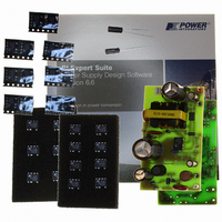
Description
KIT DESIGN REF TINYSWITCH-III
Manufacturer
Power Integrations
Series
TinySwitch®-IIIr
Specifications of RDK-91
Main Purpose
AC/DC, Primary Side
Outputs And Type
1, Non-Isolated
Power - Output
12W
Voltage - Output
12V
Current - Output
1A
Voltage - Input
85 ~ 265VAC
Regulator Topology
Flyback
Board Type
Fully Populated
Utilized Ic / Part
TNY274, TNY275, TNY276, TNY277, TNY278, TNY279, TNY280
Product
Accessories & Kits
Lead Free Status / RoHS Status
Lead free / RoHS Compliant
Frequency - Switching
-
Other names
596-1194


15 Extended and Reduced Current Limit (I
Additional capacitors (C8 and C9 on the BOM in Section 6) have been included in the
DAK-91 kit for the convenience of trying out the I
TNY278PN in the RD-91 reference board. When C7 (0.1 µF) is replaced with a 10 µF
capacitor (C9), the TNY278PN will operate in the I
maximum primary current limit from the standard maximum limit of 0.55 A to 0.65 A
(equal to that of a TNY279PN). This allows a TNY278PN to deliver from 15% to 25%
more output power (depending on the output voltage and current).
CAUTION: Because RD-91 was designed for standard I
loaded with more than 1.25 A at an elevated temperature for very long (a few minutes)
when verifying the performance of TNY278PN in the I
components (transformer, input bulk capacitors, output diode, output capacitors and
primary clamp network) are not sized for sustained operation at more than 12 W.
When C7 is replaced with a 1 µF capacitor (C8), the TNY278PN will operate in the I
1 mode, which reduces the maximum current limit from the standard maximum limit of
0.55 A to 0.45 A (equal to that of a TNY277PN). Although this reduces the maximum
output power that the supply can deliver, it typically will increase the efficiency, especially
at lower output power levels. To take the fullest advantage of the increase in efficiency
that can be obtained from I
redesigned slightly.
16 TNY277PN and TNY279PN Operation in RD-91
A TNY277PN device used in the I
in the RD-91 reference board, and deliver output power equal to that of a TNY278PN
device. This flexibility allows a design engineer the option of using a lower cost part in
applications with less demanding thermal requirements.
A TNY279PN device used in the I
the same output power as a TNY278PN in the standard I
improve efficiency and lower the temperature rise of the device, which can give greater
thermal margin to a design that must operate in high ambient temperature environments.
Power Integrations
Tel: +1 408 414 9200 Fax: +1 408 414 9201
www.powerint.com
LIMIT
–1 operation, the power transformer would need to be
LIMIT
LIMIT
–1 mode (a 1 µF installed in place of C7) will deliver
+1 mode (a 10 µF installed in place of C7) will work
LIMIT
LIMIT
LIMIT
LIMIT
) Operation
+1 mode, which increases the
+1 mode, since the other power
LIMIT
+1 and I
LIMIT
operation, It should not be
configuration. This can
LIMIT
–1 operation of
Page 34 of 37
LIMIT
–
Related parts for RDK-91
Image
Part Number
Description
Manufacturer
Datasheet
Request
R

Part Number:
Description:
KIT REF DESIGN 36-72W MOTOR DRVR
Manufacturer:
Power Integrations
Datasheet:

Part Number:
Description:
KIT REF DESIGN FOR LNK457D
Manufacturer:
Power Integrations
Datasheet:

Part Number:
Description:
REFERENCE DESIGN LINKSWITCH-PH
Manufacturer:
Power Integrations
Datasheet:

Part Number:
Description:
Specifications: Manufacturer: Power Integrations ; Output Voltage: 380 VDC ; Input / Supply Voltage (Max): 264 VAC ; Input / Supply Voltage (Min): 90 VAC ; Mounting Style: Through Hole ; Output Current: 0.913 A ; Output Power: 347 W
Manufacturer:
Power Integrations, Inc.

Part Number:
Description:
KIT REF DESIGN TOP HX FOR TOP258
Manufacturer:
Power Integrations
Datasheet:

Part Number:
Description:
Power Management Modules & Development Tools TOPSwitch-JX REF. DESIGN KIT
Manufacturer:
Power Integrations
Datasheet:
Part Number:
Description:
Power Management IC Development Tools REF DESIGN RDR-292 PFF LED STREET LIGHT
Manufacturer:
Power Integrations

Part Number:
Description:
KIT REF DESIGN FOR LNK403EG
Manufacturer:
Power Integrations
Datasheet:

Part Number:
Description:
KIT REF DESIGN FOR LNK406EG
Manufacturer:
Power Integrations
Datasheet:

Part Number:
Description:
KIT REF DESIGN DG CAPZERO
Manufacturer:
Power Integrations
Datasheet:

Part Number:
Description:
KIT REF DESIGN LINKSWITCH-CV
Manufacturer:
Power Integrations
Datasheet:

Part Number:
Description:
KIT REF DESIGN LINKSWITCH 2
Manufacturer:
Power Integrations
Datasheet:

Part Number:
Description:
KIT REF DESIGN PFS762HG
Manufacturer:
Power Integrations
Datasheet:
Part Number:
Description:
Specifications: Family: Eval Boards - DC/DC & AC/DC (Off-Line) SMPS ; Series: HiperLCS™ ; Main Purpose: DC/DC, Step Down ; Outputs and Type: 1, Isolated ; Power - Output: 150W ; Voltage - Output: 24V ; Current - Output: 6.25A ; Voltage - Input:
Manufacturer:
Power Integrations, Inc.
Datasheet:

Part Number:
Description:
KIT REF DESIGN 1.2W PS TN FAMILY
Manufacturer:
Power Integrations
Datasheet: