RDK-91 Power Integrations, RDK-91 Datasheet - Page 17
RDK-91
Manufacturer Part Number
RDK-91
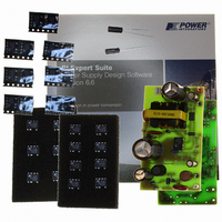
Description
KIT DESIGN REF TINYSWITCH-III
Manufacturer
Power Integrations
Series
TinySwitch®-IIIr
Specifications of RDK-91
Main Purpose
AC/DC, Primary Side
Outputs And Type
1, Non-Isolated
Power - Output
12W
Voltage - Output
12V
Current - Output
1A
Voltage - Input
85 ~ 265VAC
Regulator Topology
Flyback
Board Type
Fully Populated
Utilized Ic / Part
TNY274, TNY275, TNY276, TNY277, TNY278, TNY279, TNY280
Product
Accessories & Kits
Lead Free Status / RoHS Status
Lead free / RoHS Compliant
Frequency - Switching
-
Other names
596-1194


8 Transformer Spreadsheet
ENTER APPLICATION VARIABLES
VACMIN
VACMAX
fL
VO
IO
Power
n
Z
tC
CIN
ENTER TinySwitch-III VARIABLES
TinySwitch-III
Chosen Device
Chose Configuration
ILIMITMIN
ILIMITTYP
ILIMITMAX
fSmin
I^2fmin
VOR
VDS
VD
KP
KP_TRANSIENT
ENTER BIAS WINDING VARIABLES
VB
NB
VZOV
UVLO VARIABLES
V_UV_TARGET
V_UV_ACTUAL
RUV_IDEAL
RUV_ACTUAL
ENTER TRANSFORMER CORE/CONSTRUCTION VARIABLES
Core Type
Core
Bobbin
AE
LE
AL
Page 17 of 37
ACDC_TinySwitch-III
_011906; Rev.0.27;
Integrations 2006
Copyright Power
TNY278
STD
EE25
INPUT
101.00
12.00
28.80
1.00
0.71
0.50
3.00
265
85
50
92
TNY278
INFO
EE25
EE25_BOBBIN
TNY278
Standard
Current Limit
EE25
OUTPUT
124000 Hertz
35.937 A^2kHz
0.512 Amps
0.550 Amps
0.588 Amps
22.00 Volts
12.13
28.00 Volts
92.00 Volts
92.20 Volts
0.404 cm^2
1420 nH/T^2
28.8
0.60
0.38
3.59 Mohms
3.60 Mohms
7.34 cm
101 Volts
0.7 Volts
12
10 Volts
UNIT
Volts
Volts
Hertz
Volts
Amps
Watts
mSeconds
uFarads
P/N:
P/N:
Tel: +1 408 414 9200 Fax: +1 408 414 9201
Power Supply Output Current (corresponding to
I^2f (product of current limit squared and frequency
TinySwitch-III on-state Drain to Source Voltage
ACDC_TinySwitch-III_011906_Rev0-27.xls;
TinySwitch-III Continuous/Discontinuous
Flyback Transformer Design Spreadsheet
RD91 - 12 V, 1 A, Universal Input
Minimum AC Input Voltage
Maximum AC Input Voltage
AC Mains Frequency
Output Voltage (at continuous power)
peak power)
Continuous Output Power
Efficiency Estimate at output terminals. Unter 0.7 if
no better data available
Z Factor. Ratio of secondary side losses to the total
losses in the power supply. Use 0.5 if no better data
available
Bridge Rectifier Conduction Time Estimate
Input Capacitance
User defined TinySwitch-III
Enter "RED" for reduced current limit (sealed
adapters), "STD" for standard current limt or "INC"
for increased current limit (peak or higher power
applications)
Minimum Current Limit
Maximum Current Limit
Minimum Device Switching Frequency
is trimmed for tighter tolerance)
Reflected Output Voltage (VOR < 135 V
Recommended)
Output Winding Diode Forward Voltage Drop
Ripple to Peak Current Ratio (KP < 6)
Transient Ripple to Peak Current Ratio. Ensure
KP_TRANSIENT > 0.25
Bias Winding Voltage
Bias Winding Number of Turns
Over Voltage Protection zener diode.
Target under-voltage threshold, above which the
power supply with start
Typical start-up voltage based on standard value of
RUV_ACTUAL
Calculated value for UV Lockout resistor
Closest standard value of resistor to RUV_IDEAL
User-Selected transformer core
PC40EE25-Z
EE25_BOBBIN
Core Effective Cross Sectional Area
Core Effective Path Length
Ungapped Core Effective Inductance
Power Integrations
www.powerint.com
Related parts for RDK-91
Image
Part Number
Description
Manufacturer
Datasheet
Request
R

Part Number:
Description:
KIT REF DESIGN 36-72W MOTOR DRVR
Manufacturer:
Power Integrations
Datasheet:

Part Number:
Description:
KIT REF DESIGN FOR LNK457D
Manufacturer:
Power Integrations
Datasheet:

Part Number:
Description:
REFERENCE DESIGN LINKSWITCH-PH
Manufacturer:
Power Integrations
Datasheet:

Part Number:
Description:
Specifications: Manufacturer: Power Integrations ; Output Voltage: 380 VDC ; Input / Supply Voltage (Max): 264 VAC ; Input / Supply Voltage (Min): 90 VAC ; Mounting Style: Through Hole ; Output Current: 0.913 A ; Output Power: 347 W
Manufacturer:
Power Integrations, Inc.

Part Number:
Description:
KIT REF DESIGN TOP HX FOR TOP258
Manufacturer:
Power Integrations
Datasheet:

Part Number:
Description:
Power Management Modules & Development Tools TOPSwitch-JX REF. DESIGN KIT
Manufacturer:
Power Integrations
Datasheet:
Part Number:
Description:
Power Management IC Development Tools REF DESIGN RDR-292 PFF LED STREET LIGHT
Manufacturer:
Power Integrations

Part Number:
Description:
KIT REF DESIGN FOR LNK403EG
Manufacturer:
Power Integrations
Datasheet:

Part Number:
Description:
KIT REF DESIGN FOR LNK406EG
Manufacturer:
Power Integrations
Datasheet:

Part Number:
Description:
KIT REF DESIGN DG CAPZERO
Manufacturer:
Power Integrations
Datasheet:

Part Number:
Description:
KIT REF DESIGN LINKSWITCH-CV
Manufacturer:
Power Integrations
Datasheet:

Part Number:
Description:
KIT REF DESIGN LINKSWITCH 2
Manufacturer:
Power Integrations
Datasheet:

Part Number:
Description:
KIT REF DESIGN PFS762HG
Manufacturer:
Power Integrations
Datasheet:
Part Number:
Description:
Specifications: Family: Eval Boards - DC/DC & AC/DC (Off-Line) SMPS ; Series: HiperLCS™ ; Main Purpose: DC/DC, Step Down ; Outputs and Type: 1, Isolated ; Power - Output: 150W ; Voltage - Output: 24V ; Current - Output: 6.25A ; Voltage - Input:
Manufacturer:
Power Integrations, Inc.
Datasheet:

Part Number:
Description:
KIT REF DESIGN 1.2W PS TN FAMILY
Manufacturer:
Power Integrations
Datasheet: