RDK-91 Power Integrations, RDK-91 Datasheet
RDK-91
Specifications of RDK-91


Related parts for RDK-91


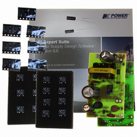
RDK-91 Summary of contents
Page 1
... Engineering Prototype Report for RDK-91 –12 W Power Supply Using Title TinySwitch 85-265 VAC Input Output Specification TinySwitch-III Reference Design (RDK-91) Application Power Integrations Applications Department Author Document RDR-91 Number 18-July-2007 Date 1.2 Revision Summary and Features ® • – Meets all existing and proposed harmonized energy efficiency ...
Page 2
... The products and applications illustrated herein (including circuits external to the products and transformer construction) may be covered by one or more U.S. and foreign patents or potentially by pending U.S. and foreign patent applications assigned to Power Integrations. A complete list of Power Integrations’ patents may be found at www.powerint.com. ...
Page 3
... Ripple Measurement Technique.................................................................28 11.5.2 Measurement Results.................................................................................29 11.6 Overvoltage Shutdown ......................................................................................29 12 Line Surge.............................................................................................................30 13 Conducted EMI .....................................................................................................31 13.1 115 VAC, Full Load............................................................................................31 13.2 230 VAC, Full Load............................................................................................32 14 Audible Noise ........................................................................................................33 Page Power Integrations Tel: +1 408 414 9200 Fax: +1 408 414 9201 www.powerint.com ...
Page 4
... Important Note: Although this board was designed to satisfy safety isolation requirements, it has not been agency approved. Therefore, all testing should be performed using an isolation transformer to provide the AC input to the power supply. Power Integrations Tel: +1 408 414 9200 Fax: +1 408 414 9201 www.powerint.com ) Operation ........................................34 ...
Page 5
... TinySwitch-III family. These include easy adjustment of the device current limit for increased output power or higher efficiency operation, and a latched output overvoltage shutdown Figure 1 – RD-91 Populated Circuit Board Photographs. Page contains the complete - - + Tel: +1 408 414 9200 Fax: +1 408 414 9201 + Power Integrations www.powerint.com ...
Page 6
... Overvoltage Shutdown Efficiency Full Load Required average efficiency at 25, 50, 75 and 100 % of P OUT Environmental Conducted EMI Safety Surge (Differential) Surge (Common mode) Ambient Temperature Power Integrations Tel: +1 408 414 9200 Fax: +1 408 414 9201 www.powerint.com Symbol Min Typ Max 85 265 ...
Page 7
... Circuit Diagram Page Figure 2 – RD-91 Circuit Diagram. Tel: +1 408 414 9200 Fax: +1 408 414 9201 Power Integrations www.powerint.com ...
Page 8
... When the standard production technique of dip varnishing is used for the transformer, audible noise is practically eliminated. Power Integrations Tel: +1 408 414 9200 Fax: +1 408 414 9201 www.powerint.com Capacitors C1 and C2 filter the rectified DC. ...
Page 9
... MOSFET turns off. When combined with the IC’s frequency jitter function, these techniques produce excellent conducted and radiated EMI performance (see Section 12 of this report). Page The overvoltage Power Integrations Tel: +1 408 414 9200 Fax: +1 408 414 9201 www.powerint.com ...
Page 10
... MOSFET switching until the input voltage rises above the under-voltage lockout threshold. Power Integrations Tel: +1 408 414 9200 Fax: +1 408 414 9201 www.powerint.com Page ...
Page 11
... PCB Layout Figure 3 – Printed Circuit Board Layout (3.2 × 1.8 inches). Page Power Integrations Tel: +1 408 414 9200 Fax: +1 408 414 9201 www.powerint.com ...
Page 12
... R8 1%, 1/4 W, Metal Film 29 1 RV1 275 mm, RADIAL Transformer, 10 Pins, Vertical TinySwitch-III, TNY278PN, DIP-8C Power Integrations Tel: +1 408 414 9200 Fax: +1 408 414 9201 www.powerint.com Mfg Mfg Part Number Nippon Chemi- EKXG401ELL6R8M Con J16S Nippon Chemi- EKMX401ELL220M Con L20S Vishay/Spragu 562R5HKMS10 ...
Page 13
... V, 600 W, 5%, TVS, DO204AC (DO-15 VR2 28 V, 5%, 500 mW, DO- VR3 11 V, 500 mW, 5%, DO-35 * Optional components Note – All parts are RoHS compliant Page NEC PS2501-1-H-A LittlelFuse P6KE150A Diodes Inc 1N5255B-T Vishay BZX55C11 Power Integrations Tel: +1 408 414 9200 Fax: +1 408 414 9201 www.powerint.com ...
Page 14
... Bias WDG # AWG X3 Bias AWG X3 WDG # 4 7.2 Electrical Specifications Electrical Strength Primary Inductance Resonant Frequency Primary Leakage Inductance Power Integrations Tel: +1 408 414 9200 Fax: +1 408 414 9201 www.powerint.com Figure 4 – Transformer Electrical Diagram. 1 second, 60 Hz, from Pins 1-5 to Pins 6-10 Pins 1-3, all other windings open, measured at 100 kHz, 0 ...
Page 15
... Varnish (applied by dipping only, not vacuum impregnation) [10] 7.4 Transformer Build Diagram Margin Tape Page Description Figure 5 – Transformer Build Diagram. Tel: +1 408 414 9200 Fax: +1 408 414 9201 2 of 335 nH layer of tape Bias Winding Primary Winding 1 layer of tape Cancellation Winding No Connect Power Integrations www.powerint.com ...
Page 16
... Finish on Pin 6. Secondary Winding 3 Layers of tape [8] for insulation. Outer Insulation Assemble and secure core halves using item [1] and item [9] Core Assembly Dip varnish using item [10] (do not vacuum impregnate) Varnish Power Integrations Tel: +1 408 414 9200 Fax: +1 408 414 9201 www.powerint.com Page ...
Page 17
... Closest standard value of resistor to RUV_IDEAL User-Selected transformer core EE25 PC40EE25-Z EE25 P/N: EE25_BOBBIN EE25_BOBBIN P/N: 0.404 cm^2 Core Effective Cross Sectional Area 7.34 cm Core Effective Path Length 1420 nH/T^2 Ungapped Core Effective Inductance Tel: +1 408 414 9200 Fax: +1 408 414 9201 Power Integrations www.powerint.com ...
Page 18
... DIA AWG CM CMA TRANSFORMER SECONDARY DESIGN PARAMETERS Lumped parameters ISP ISRMS IRIPPLE CMS AWGS VOLTAGE STRESS PARAMETERS VDRAIN PIVS Power Integrations Tel: +1 408 414 9200 Fax: +1 408 414 9201 www.powerint.com 10 Volts 375 Volts 0.59 0.24 Amps 0.5120 Amps 0.3075 Amps 0.33 Amps ...
Page 19
... Figure 6 – Efficiency vs. Output Current, Room Temperature, 60 Hz. Page CEC/ENERGY STAR EPS Requirement 0.3 0.4 0.5 0.6 Output Current (A) Tel: +1 408 414 9200 Fax: +1 408 414 9201 85 VAC 115 VAC 230 VAC 265 VAC 0.7 0.8 0.9 1 Power Integrations www.powerint.com ...
Page 20
... Energy Star standard). For the latest, up-to-date information on energy efficiency regulations, please visit the PI Green Room, at: http://www.powerint.com/greenroom/regulations.htm Power Integrations Tel: +1 408 414 9200 Fax: +1 408 414 9201 www.powerint.com ) Minimum Efficiency in Active Mode of Operation O 0.49 × ...
Page 21
... Figure 8 – No-load Input Power vs. Input Line Voltage, Room Temperature, 60 Hz, with Bias Winding. Page 145 165 185 205 Input VAC 145 165 185 205 Input Voltage (VAC) Tel: +1 408 414 9200 Fax: +1 408 414 9201 225 245 265 225 245 265 Power Integrations www.powerint.com ...
Page 22
... Figure 9 – Available Output Power for 1, 2 and 3 Watts of Input Power. Power Integrations Tel: +1 408 414 9200 Fax: +1 408 414 9201 www.powerint.com 2.2 W for 3 W input at 230 VAC 1.4 W for 2 W input at 230 VAC 0.65 W for 1 W input at 230 VAC ...
Page 23
... Figure 10 – Load and Line Regulation, Room Temperature. Page 0.3 0.4 0.5 0.6 Output Current (A) Tel: +1 408 414 9200 Fax: +1 408 414 9201 85 VAC 115 VAC 230 VAC 265 VAC 0.7 0.8 0.9 1 Power Integrations www.powerint.com ...
Page 24
... These results show that all key components have an acceptable rise in temperature. 85 VAC Load, 22 °C Ambient Figure 11 – Infrared Thermograph of Open Frame Operation, at Room Temperature. Power Integrations Tel: +1 408 414 9200 Fax: +1 408 414 9201 www.powerint.com Temperature (°C) ...
Page 25
... VAC, Full Load. Figure µs / div. V DRAIN Page – 230 VAC, Full Load. Figure 13 Upper 0 div. DRAIN Lower 100 V / div. DRAIN – 230 VAC, Full Load. Figure 15 , 100 V, 20 µs / div. V DRAIN Power Integrations Tel: +1 408 414 9200 Fax: +1 408 414 9201 www.powerint.com ...
Page 26
... Figure 18 – 90 VAC Input and Maximum Load. , 100 V & 100 µs / div. Upper: V DRAIN Lower 0 div. DRAIN Power Integrations Tel: +1 408 414 9200 Fax: +1 408 414 9201 www.powerint.com Figure 17 – Start-Up Profile, 230 VAC. Fast trace is no-load rise time Slower trace is maximum load (12 Ω div. ...
Page 27
... Figure 20 – Transient Response, 115 VAC, 50-100-50% Load Step. Upper mV/div. OUT Lower div. OUT Page Figure 21 – Transient Response, 230 VAC, 50-100-50% Load Step. Upper mV/div. OUT Lower div. OUT Power Integrations Tel: +1 408 414 9200 Fax: +1 408 414 9201 www.powerint.com ...
Page 28
... Figure 22 – Oscilloscope Probe Prepared for Ripple Measurement (End Cap and Ground Lead Removed). Power Integrations Tel: +1 408 414 9200 Fax: +1 408 414 9201 www.powerint.com ...
Page 29
... Overvoltage Shutdown Figure 25 – Overvoltage Shutdown. 265 VAC, No Load div. Page Figure 24 – Ripple, 115 VAC, Full Load. 20 µ div. Figure 26 – Overvoltage Shutdown. 265 VAC, Full Load div. Power Integrations Tel: +1 408 414 9200 Fax: +1 408 414 9201 www.powerint.com ...
Page 30
... Surge Phase Angle Voltage 1 kV 90˚ Differential 2 kV Common 90˚ Mode Unit passed under all test conditions. Power Integrations Tel: +1 408 414 9200 Fax: +1 408 414 9201 www.powerint.com Generator Number of Strikes Impedance 2 Ω Ω 10 Test Result PASS ...
Page 31
... VAC, Full Load Line Artificial Hand Connected to Output Return Output Floating Figure 27 Page Artificial Hand Connected to Output Return Output Floating – Conducted EMI at 115 VAC. Tel: +1 408 414 9200 Fax: +1 408 414 9201 Neutral Power Integrations www.powerint.com ...
Page 32
... VAC, Full Load Line Artificial Hand Connected to Output Return Output Floating Power Integrations Tel: +1 408 414 9200 Fax: +1 408 414 9201 www.powerint.com Artificial Hand Connected to Output Return – Conducted EMI at 230 VAC. Figure 28 Neutral Output Floating Page ...
Page 33
... Hz Thick Data Axis 1 Fft.Ch.1 Ampl Left Arts_audionoise1.at2 = 120 VAC OUT 08/17/05 15:09: 10k 12k 14k 16k 18k Hz Thick Data Axis 1 Fft.Ch.1 Ampl Left Arts_audionoise1.at2 = 230 VAC =1.2 A. OUT Power Integrations www.powerint.com 20k 22k 20k 22k ...
Page 34
... TNY278PN in the standard I improve efficiency and lower the temperature rise of the device, which can give greater thermal margin to a design that must operate in high ambient temperature environments. Power Integrations Tel: +1 408 414 9200 Fax: +1 408 414 9201 www.powerint.com ...
Page 35
... Point on PCB to Apply Short Circuit to Trigger OV Shutdown. Figure 33 Page The oscilloscope will capture the output Short these points to test OVP functionality Power Integrations Tel: +1 408 414 9200 Fax: +1 408 414 9201 www.powerint.com ...
Page 36
... Revision History Date Author 25-Jan-06 JAJ 07-Feb-06 JAJ 18-July-2007 SGK Power Integrations Tel: +1 408 414 9200 Fax: +1 408 414 9201 www.powerint.com Revision Description & changes 1.0 Formatted for Final Release 1.1 Formatted and corrected measurement scales / div. 1.2 Updated for RoHS compliance, changed to RD-91 ...
Page 37
... For the latest updates, visit our website: www.powerint.com Power Integrations reserves the right to make changes to its products at any time to improve reliability or manufacturability. Power Integrations does not assume any liability arising from the use of any device or circuit described herein. POWER INTEGRATIONS MAKES NO WARRANTY HEREIN AND SPECIFICALLY DISCLAIMS ALL WARRANTIES INCLUDING, WITHOUT LIMITATION, THE IMPLIED WARRANTIES OF MERCHANTABILITY, FITNESS FOR A PARTICULAR PURPOSE, AND NON-INFRINGEMENT OF THIRD PARTY RIGHTS ...