RDK-91 Power Integrations, RDK-91 Datasheet - Page 3
RDK-91
Manufacturer Part Number
RDK-91
Description
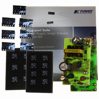
KIT DESIGN REF TINYSWITCH-III
Manufacturer
Power Integrations
Series
TinySwitch®-IIIr
Specifications of RDK-91
Main Purpose
AC/DC, Primary Side
Outputs And Type
1, Non-Isolated
Power - Output
12W
Voltage - Output
12V
Current - Output
1A
Voltage - Input
85 ~ 265VAC
Regulator Topology
Flyback
Board Type
Fully Populated
Utilized Ic / Part
TNY274, TNY275, TNY276, TNY277, TNY278, TNY279, TNY280
Product
Accessories & Kits
Lead Free Status / RoHS Status
Lead free / RoHS Compliant
Frequency - Switching
-
Other names
596-1194


Table of Contents
1
2
3
4
5
6
7
8
9
10
11
12
13
14
Page 3 of 37
4.1
4.2
4.3
4.4
4.5
4.6
4.7
4.8
7.1
7.2
7.3
7.4
7.5
9.1
9.2
9.3
9.4
9.5
9.6
11.1
11.2
11.3
11.4
11.5
11.6
13.1
13.2
Introduction .................................................................................................................5
Power Supply Specification ........................................................................................6
Circuit Diagram ...........................................................................................................7
Circuit Description.......................................................................................................8
PCB Layout...............................................................................................................11
Bill of Materials .........................................................................................................12
Transformer Specification .........................................................................................14
Transformer Spreadsheet .........................................................................................17
Performance Data.....................................................................................................19
9.6.1
11.5.1
11.5.2
Thermal Performance............................................................................................24
Waveforms ............................................................................................................25
Line Surge.............................................................................................................30
Conducted EMI .....................................................................................................31
Audible Noise ........................................................................................................33
Input Rectification and Filtering ...........................................................................8
TNY278PN Operation..........................................................................................8
Output Rectification and Filtering.........................................................................9
Feedback and Output Voltage Regulation ...........................................................9
Output Overvoltage Shutdown.............................................................................9
EMI Design Aspects ............................................................................................9
Peak Primary Current Limit Selection ................................................................10
UV Lockout ........................................................................................................10
Electrical Diagram..............................................................................................14
Electrical Specifications .....................................................................................14
Materials ............................................................................................................15
Transformer Build Diagram................................................................................15
Transformer Construction ..................................................................................16
Efficiency ...........................................................................................................19
Active Mode CEC Measurement Data ...............................................................20
No-load Input Power (R8 not installed: no bias winding supplementation) ........21
No-load Input Power (with R8 and bias winding supplementation)....................21
Available Standby Output Power .......................................................................22
Regulation .........................................................................................................23
Drain Voltage and Current, Normal Operation...................................................25
Output Voltage Start-Up Profile .........................................................................26
Drain Voltage and Current Start-Up Profile........................................................26
Load Transient Response (75% to 100% Load Step)........................................27
Output Ripple Measurements ............................................................................28
Overvoltage Shutdown ......................................................................................29
115 VAC, Full Load............................................................................................31
230 VAC, Full Load............................................................................................32
Load and Line.............................................................................................23
Ripple Measurement Technique.................................................................28
Measurement Results.................................................................................29
Tel: +1 408 414 9200 Fax: +1 408 414 9201
Power Integrations
www.powerint.com
Related parts for RDK-91
Image
Part Number
Description
Manufacturer
Datasheet
Request
R

Part Number:
Description:
KIT REF DESIGN 36-72W MOTOR DRVR
Manufacturer:
Power Integrations
Datasheet:

Part Number:
Description:
KIT REF DESIGN FOR LNK457D
Manufacturer:
Power Integrations
Datasheet:

Part Number:
Description:
REFERENCE DESIGN LINKSWITCH-PH
Manufacturer:
Power Integrations
Datasheet:

Part Number:
Description:
Specifications: Manufacturer: Power Integrations ; Output Voltage: 380 VDC ; Input / Supply Voltage (Max): 264 VAC ; Input / Supply Voltage (Min): 90 VAC ; Mounting Style: Through Hole ; Output Current: 0.913 A ; Output Power: 347 W
Manufacturer:
Power Integrations, Inc.

Part Number:
Description:
KIT REF DESIGN TOP HX FOR TOP258
Manufacturer:
Power Integrations
Datasheet:

Part Number:
Description:
Power Management Modules & Development Tools TOPSwitch-JX REF. DESIGN KIT
Manufacturer:
Power Integrations
Datasheet:
Part Number:
Description:
Power Management IC Development Tools REF DESIGN RDR-292 PFF LED STREET LIGHT
Manufacturer:
Power Integrations

Part Number:
Description:
KIT REF DESIGN FOR LNK403EG
Manufacturer:
Power Integrations
Datasheet:

Part Number:
Description:
KIT REF DESIGN FOR LNK406EG
Manufacturer:
Power Integrations
Datasheet:

Part Number:
Description:
KIT REF DESIGN DG CAPZERO
Manufacturer:
Power Integrations
Datasheet:

Part Number:
Description:
KIT REF DESIGN LINKSWITCH-CV
Manufacturer:
Power Integrations
Datasheet:

Part Number:
Description:
KIT REF DESIGN LINKSWITCH 2
Manufacturer:
Power Integrations
Datasheet:

Part Number:
Description:
KIT REF DESIGN PFS762HG
Manufacturer:
Power Integrations
Datasheet:
Part Number:
Description:
Specifications: Family: Eval Boards - DC/DC & AC/DC (Off-Line) SMPS ; Series: HiperLCS™ ; Main Purpose: DC/DC, Step Down ; Outputs and Type: 1, Isolated ; Power - Output: 150W ; Voltage - Output: 24V ; Current - Output: 6.25A ; Voltage - Input:
Manufacturer:
Power Integrations, Inc.
Datasheet:

Part Number:
Description:
KIT REF DESIGN 1.2W PS TN FAMILY
Manufacturer:
Power Integrations
Datasheet: