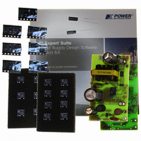
RDK-91 Power Integrations, RDK-91 Datasheet - Page 16
RDK-91
Manufacturer Part Number
RDK-91
Description
KIT DESIGN REF TINYSWITCH-III
Manufacturer
Power Integrations
Series
TinySwitch®-IIIr
Specifications of RDK-91
Main Purpose
AC/DC, Primary Side
Outputs And Type
1, Non-Isolated
Power - Output
12W
Voltage - Output
12V
Current - Output
1A
Voltage - Input
85 ~ 265VAC
Regulator Topology
Flyback
Board Type
Fully Populated
Utilized Ic / Part
TNY274, TNY275, TNY276, TNY277, TNY278, TNY279, TNY280
Product
Accessories & Kits
Lead Free Status / RoHS Status
Lead free / RoHS Compliant
Frequency - Switching
-
Other names
596-1194


7.5 Transformer Construction
Cancellation Winding
Secondary Winding
Primary winding
Outer Insulation
Core Assembly
Bobbin Set Up
Bias Winding
Bias Winding
Margin Tape
Margin Tape
Orientation
Insulation
Insulation
Insulation
Insulation
Varnish
WD #3
WD #4
WD #5
Power Integrations
Tel: +1 408 414 9200 Fax: +1 408 414 9201
www.powerint.com
WD#2
WD1
Set up the bobbin with its pins oriented to the left hand side.
Apply 2.0 mm margin at the pin side of bobbin using item [6]. Match
combined height of shield, primary, and bias windings.
Start at Pin 1. Wind 14 bifilar turns of item [3] from left to right. Wind with
tight tension across entire bobbin evenly. Cut the ends of the bifilar and
leave floating.
1 Layer of tape [7] for insulation.
Start at pin 3. Wind 28 turns of item [3] from left to right. Apply 1 Layer of
tape [7] for insulation. Wind another 28 turns from right to left. Wind with
tight tension across entire bobbin evenly. Finish at Pin 1.
1 Layer of tape [7] for insulation.
Start at Pin 4, wind 6 trifilar turns of item [5]. Wind from left to right with
tight tension. Wind uniformly, in a single layer across entire width of
bobbin. Finish on Pin 2.
1 Layer of tape [7] for insulation.
Start at Pin 2, wind 6 trifilar turns of item [5] from left to right with tight
tension. Wind uniformly, in a single layer across entire width of bobbin.
Finish on Pin 5.
1 Layer of tape [8] for insulation.
Apply 2.0 mm margin at the pin side of bobbin using item [6]. Match
combined height of secondary windings.
Start at Pin 8, wind 7 turns of item [5] from left to right. Wind uniformly, in
a single layer across entire bobbin evenly. Finish on Pin 6.
3 Layers of tape [8] for insulation.
Assemble and secure core halves using item [1] and item [9]
Dip varnish using item [10] (do not vacuum impregnate)
Page 16 of 37
Related parts for RDK-91
Image
Part Number
Description
Manufacturer
Datasheet
Request
R

Part Number:
Description:
KIT REF DESIGN 36-72W MOTOR DRVR
Manufacturer:
Power Integrations
Datasheet:

Part Number:
Description:
KIT REF DESIGN FOR LNK457D
Manufacturer:
Power Integrations
Datasheet:

Part Number:
Description:
REFERENCE DESIGN LINKSWITCH-PH
Manufacturer:
Power Integrations
Datasheet:

Part Number:
Description:
Specifications: Manufacturer: Power Integrations ; Output Voltage: 380 VDC ; Input / Supply Voltage (Max): 264 VAC ; Input / Supply Voltage (Min): 90 VAC ; Mounting Style: Through Hole ; Output Current: 0.913 A ; Output Power: 347 W
Manufacturer:
Power Integrations, Inc.

Part Number:
Description:
KIT REF DESIGN TOP HX FOR TOP258
Manufacturer:
Power Integrations
Datasheet:

Part Number:
Description:
Power Management Modules & Development Tools TOPSwitch-JX REF. DESIGN KIT
Manufacturer:
Power Integrations
Datasheet:
Part Number:
Description:
Power Management IC Development Tools REF DESIGN RDR-292 PFF LED STREET LIGHT
Manufacturer:
Power Integrations

Part Number:
Description:
KIT REF DESIGN FOR LNK403EG
Manufacturer:
Power Integrations
Datasheet:

Part Number:
Description:
KIT REF DESIGN FOR LNK406EG
Manufacturer:
Power Integrations
Datasheet:

Part Number:
Description:
KIT REF DESIGN DG CAPZERO
Manufacturer:
Power Integrations
Datasheet:

Part Number:
Description:
KIT REF DESIGN LINKSWITCH-CV
Manufacturer:
Power Integrations
Datasheet:

Part Number:
Description:
KIT REF DESIGN LINKSWITCH 2
Manufacturer:
Power Integrations
Datasheet:

Part Number:
Description:
KIT REF DESIGN PFS762HG
Manufacturer:
Power Integrations
Datasheet:
Part Number:
Description:
Specifications: Family: Eval Boards - DC/DC & AC/DC (Off-Line) SMPS ; Series: HiperLCS™ ; Main Purpose: DC/DC, Step Down ; Outputs and Type: 1, Isolated ; Power - Output: 150W ; Voltage - Output: 24V ; Current - Output: 6.25A ; Voltage - Input:
Manufacturer:
Power Integrations, Inc.
Datasheet:

Part Number:
Description:
KIT REF DESIGN 1.2W PS TN FAMILY
Manufacturer:
Power Integrations
Datasheet: