SOUNDBITE Freescale Semiconductor, SOUNDBITE Datasheet - Page 65
SOUNDBITE
Manufacturer Part Number
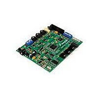
SOUNDBITE
Description
BOARD DEMO AUDIO DEVELOPMENT
Manufacturer
Freescale Semiconductor
Series
Symphony™ soundBiter
Datasheet
1.DSPB56371AF180.pdf
(68 pages)
Specifications of SOUNDBITE
Main Purpose
Audio, Audio Processing
Utilized Ic / Part
DSPB56371
Primary Attributes
Up to 8 channels of digital audio
Secondary Attributes
USB, I2C, SPI Interface
Processor To Be Evaluated
DSP56371
Data Bus Width
24 bit
Interface Type
USB
Lead Free Status / RoHS Status
Lead free / RoHS Compliant
Embedded
-
Lead Free Status / Rohs Status
Lead free / RoHS Compliant


21.1 Power Consumption Considerations
Power dissipation is a key issue in portable DSP applications. Some of the factors which affect current
consumption are described in this section. Most of the current consumed by CMOS devices is alternating
current (ac), which is charging and discharging the capacitances of the pins and internal nodes.
Current consumption is described by the following formula:
The maximum internal current (I
on best-case operation conditions, which is not necessarily a real application case. The typical internal
current (I
For applications that require very low current consumption, do the following:
One way to evaluate power consumption is to use a current per MIPS measurement methodology to
minimize specific board effects (for example, to compensate for measured board current not caused by the
DSP). Use the test algorithm, specific test current measurements, and the following equation to derive the
current per MIPS value.
Freescale Semiconductor
•
•
•
Power Consumption Example
For a GPIO address pin loaded with 50 pF capacitance, operating at 3.3 V, and with a 150 MHz clock, toggling at
its maximum possible rate (75 MHz), the current consumption is
At power-up, ensure that the voltage difference between the 3.3 V tolerant pins and the chip V
never exceeds a 3.00 V.
where
Minimize the number of pins that are switching.
Minimize the capacitive load on the pins.
where :
F1 should be significantly less than F2. For example, F2 could be 66 MHz and F1 could be
33 MHz. The degree of difference between F1 and F2 determines the amount of precision
with which the current rating can be determined for an application.
CCItyp
) value reflects the average switching of the internal buses on typical operating conditions.
C=node/pin capacitance
V=voltage swing
f=frequency of node/pin toggle
I
I
F2=high frequency (any specified operating frequency)
F1=low frequency (any specified operating frequency lower than F2)
typF2
typF1
=current at F2
=current at F1
I/MIPS = I/MHz = (I
CCI
I
max) value reflects the typical possible switching of the internal buses
=
50
DSP56371 Data Sheet, Rev. 4.1
x
10 12
I
=
–
C
x
typF2
×
3.3
NOTE
V
×
x
75
- I
f
typF1
x
10 6
)/(F2 - F1)
=
12.375mA
Electrical Design Considerations
Eqn. 7
Eqn. 6
Eqn. 8
CC
65
Related parts for SOUNDBITE
Image
Part Number
Description
Manufacturer
Datasheet
Request
R

Part Number:
Description:
Manufacturer:
Freescale Semiconductor, Inc
Datasheet:
Part Number:
Description:
Manufacturer:
Freescale Semiconductor, Inc
Datasheet:
Part Number:
Description:
Manufacturer:
Freescale Semiconductor, Inc
Datasheet:
Part Number:
Description:
Manufacturer:
Freescale Semiconductor, Inc
Datasheet:
Part Number:
Description:
Manufacturer:
Freescale Semiconductor, Inc
Datasheet:
Part Number:
Description:
Manufacturer:
Freescale Semiconductor, Inc
Datasheet:
Part Number:
Description:
Manufacturer:
Freescale Semiconductor, Inc
Datasheet:
Part Number:
Description:
Manufacturer:
Freescale Semiconductor, Inc
Datasheet:
Part Number:
Description:
Manufacturer:
Freescale Semiconductor, Inc
Datasheet:
Part Number:
Description:
Manufacturer:
Freescale Semiconductor, Inc
Datasheet:
Part Number:
Description:
Manufacturer:
Freescale Semiconductor, Inc
Datasheet:
Part Number:
Description:
Manufacturer:
Freescale Semiconductor, Inc
Datasheet:
Part Number:
Description:
Manufacturer:
Freescale Semiconductor, Inc
Datasheet:
Part Number:
Description:
Manufacturer:
Freescale Semiconductor, Inc
Datasheet:
Part Number:
Description:
Manufacturer:
Freescale Semiconductor, Inc
Datasheet: