SOUNDBITE Freescale Semiconductor, SOUNDBITE Datasheet - Page 16
SOUNDBITE
Manufacturer Part Number
SOUNDBITE
Description
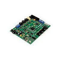
BOARD DEMO AUDIO DEVELOPMENT
Manufacturer
Freescale Semiconductor
Series
Symphony™ soundBiter
Datasheet
1.DSPB56371AF180.pdf
(68 pages)
Specifications of SOUNDBITE
Main Purpose
Audio, Audio Processing
Utilized Ic / Part
DSPB56371
Primary Attributes
Up to 8 channels of digital audio
Secondary Attributes
USB, I2C, SPI Interface
Processor To Be Evaluated
DSP56371
Data Bus Width
24 bit
Interface Type
USB
Lead Free Status / RoHS Status
Lead free / RoHS Compliant
Embedded
-
Lead Free Status / Rohs Status
Lead free / RoHS Compliant


Signal/Connection Descriptions
3.7
The SHI has five I/O signals that can be configured to allow the SHI to operate in either SPI or I
16
Signal Name
MODC/IRQC
MODD/IRQD
MODB/IRQB
RESET
Serial Host Interface
Type
Input
Input
Input
Input
During
Reset
State
Input
Input
Input
Input
Table 6. Interrupt and Mode Control (continued)
Mode Select B/External Interrupt Request B—MODB/IRQB is an active-low
Schmitt-trigger input, internally synchronized to the DSP clock. MODB/IRQB
selects the initial chip operating mode during hardware reset and becomes a
level-sensitive or negative-edge-triggered, maskable interrupt request input
during normal instruction processing. MODA, MODB, MODC and MODD select
one of 16 initial chip operating modes, latched into OMR when the RESET signal
is deasserted.
Internal Pull up resistor.
This input is 5 V tolerant.
Mode Select C/External Interrupt Request C—MODC/IRQC is an active-low
Schmitt-trigger input, internally synchronized to the DSP clock. MODC/IRQC
selects the initial chip operating mode during hardware reset and becomes a
level-sensitive or negative-edge-triggered, maskable interrupt request input
during normal instruction processing. MODA, MODB, MODC and MODD select
one of 16 initial chip operating modes, latched into OMR when the RESET signal
is deasserted.
Internal Pull up resistor.
This input is 5 V tolerant.
Mode Select D/External Interrupt Request D—MODD/IRQD is an active-low
Schmitt-trigger input, internally synchronized to the DSP clock. MODD/IRQD
selects the initial chip operating mode during hardware reset and becomes a
level-sensitive or negative-edge-triggered, maskable interrupt request input
during normal instruction processing. MODA, MODB, MODC and MODD select
one of 16 initial chip operating modes, latched into OMR when the RESET signal
is deasserted.
Internal Pull up resistor.
This input is 5 V tolerant.
Reset—RESET is an active-low, Schmitt-trigger input. When asserted, the chip
is placed in the Reset state and the internal phase generator is reset. The
Schmitt-trigger input allows a slowly rising input (such as a capacitor charging)
to reset the chip reliably. When the RESET signal is deasserted, the initial chip
operating mode is latched from the MODA, MODB, MODC and MODD inputs.
The RESET signal must be asserted during power up. A stable EXTAL signal
must be supplied while RESET is being asserted.
Internal Pull up resistor.
This input is 5 V tolerant.
DSP56371 Data Sheet, Rev. 4.1
Signal Description
Freescale Semiconductor
2
C mode.
Related parts for SOUNDBITE
Image
Part Number
Description
Manufacturer
Datasheet
Request
R

Part Number:
Description:
Manufacturer:
Freescale Semiconductor, Inc
Datasheet:
Part Number:
Description:
Manufacturer:
Freescale Semiconductor, Inc
Datasheet:
Part Number:
Description:
Manufacturer:
Freescale Semiconductor, Inc
Datasheet:
Part Number:
Description:
Manufacturer:
Freescale Semiconductor, Inc
Datasheet:
Part Number:
Description:
Manufacturer:
Freescale Semiconductor, Inc
Datasheet:
Part Number:
Description:
Manufacturer:
Freescale Semiconductor, Inc
Datasheet:
Part Number:
Description:
Manufacturer:
Freescale Semiconductor, Inc
Datasheet:
Part Number:
Description:
Manufacturer:
Freescale Semiconductor, Inc
Datasheet:
Part Number:
Description:
Manufacturer:
Freescale Semiconductor, Inc
Datasheet:
Part Number:
Description:
Manufacturer:
Freescale Semiconductor, Inc
Datasheet:
Part Number:
Description:
Manufacturer:
Freescale Semiconductor, Inc
Datasheet:
Part Number:
Description:
Manufacturer:
Freescale Semiconductor, Inc
Datasheet:
Part Number:
Description:
Manufacturer:
Freescale Semiconductor, Inc
Datasheet:
Part Number:
Description:
Manufacturer:
Freescale Semiconductor, Inc
Datasheet:
Part Number:
Description:
Manufacturer:
Freescale Semiconductor, Inc
Datasheet: