SOUNDBITE Freescale Semiconductor, SOUNDBITE Datasheet - Page 32
SOUNDBITE
Manufacturer Part Number
SOUNDBITE
Description
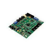
BOARD DEMO AUDIO DEVELOPMENT
Manufacturer
Freescale Semiconductor
Series
Symphony™ soundBiter
Datasheet
1.DSPB56371AF180.pdf
(68 pages)
Specifications of SOUNDBITE
Main Purpose
Audio, Audio Processing
Utilized Ic / Part
DSPB56371
Primary Attributes
Up to 8 channels of digital audio
Secondary Attributes
USB, I2C, SPI Interface
Processor To Be Evaluated
DSP56371
Data Bus Width
24 bit
Interface Type
USB
Lead Free Status / RoHS Status
Lead free / RoHS Compliant
Embedded
-
Lead Free Status / Rohs Status
Lead free / RoHS Compliant


Signal/Connection Descriptions
3.12 Timer
32
Signal
Name
TIO0
TIO1
Input or
Input or
Output
Output
Type
GPIO Input Timer 0 Schmitt-Trigger Input/Output—When timer 0 functions as an
GPIO Input Timer 1 Schmitt-Trigger Input/Output—When timer 1 functions as an
during
Reset
State
DSP56371 Data Sheet, Rev. 4.1
external event counter or in measurement mode, TIO0 is used as input.
When timer 0 functions in watchdog, timer, or pulse modulation mode,
TIO0 is used as output.
The default mode after reset is GPIO input. This can be changed to
output or configured as a timer input/output through the timer 0
control/status register (TCSR0). If TIO0 is not being used, it is
recommended to either define it as GPIO output immediately at the
beginning of operation or leave it defined as GPIO input but connected
to VDD through a pull-up resistor in order to ensure a stable logic level
at this input.
Internal Pull down resistor.
This input is 5 V tolerant.
external event counter or in measurement mode, TIO1 is used as input.
When timer 1 functions in watchdog, timer, or pulse modulation mode,
TIO1 is used as output.
The default mode after reset is GPIO input. This can be changed to
output or configured as a timer input/output through the timer 1
control/status register (TCSR1). If TIO1 is not being used, it is
recommended to either define it as GPIO output immediately at the
beginning of operation or leave it defined as GPIO input but connected
to Vdd through a pull-up resistor in order to ensure a stable logic level at
this input.
Internal Pull down resistor.
This input is 5 V tolerant.
Table 12. Timer Signal
Signal Description
Freescale Semiconductor
Related parts for SOUNDBITE
Image
Part Number
Description
Manufacturer
Datasheet
Request
R

Part Number:
Description:
Manufacturer:
Freescale Semiconductor, Inc
Datasheet:
Part Number:
Description:
Manufacturer:
Freescale Semiconductor, Inc
Datasheet:
Part Number:
Description:
Manufacturer:
Freescale Semiconductor, Inc
Datasheet:
Part Number:
Description:
Manufacturer:
Freescale Semiconductor, Inc
Datasheet:
Part Number:
Description:
Manufacturer:
Freescale Semiconductor, Inc
Datasheet:
Part Number:
Description:
Manufacturer:
Freescale Semiconductor, Inc
Datasheet:
Part Number:
Description:
Manufacturer:
Freescale Semiconductor, Inc
Datasheet:
Part Number:
Description:
Manufacturer:
Freescale Semiconductor, Inc
Datasheet:
Part Number:
Description:
Manufacturer:
Freescale Semiconductor, Inc
Datasheet:
Part Number:
Description:
Manufacturer:
Freescale Semiconductor, Inc
Datasheet:
Part Number:
Description:
Manufacturer:
Freescale Semiconductor, Inc
Datasheet:
Part Number:
Description:
Manufacturer:
Freescale Semiconductor, Inc
Datasheet:
Part Number:
Description:
Manufacturer:
Freescale Semiconductor, Inc
Datasheet:
Part Number:
Description:
Manufacturer:
Freescale Semiconductor, Inc
Datasheet:
Part Number:
Description:
Manufacturer:
Freescale Semiconductor, Inc
Datasheet: