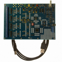
CDB5376 Cirrus Logic Inc, CDB5376 Datasheet - Page 66

CDB5376
Manufacturer Part Number
CDB5376
Description
EVALUATION BOARD FOR CS5376
Manufacturer
Cirrus Logic Inc
Datasheets
1.CS5371A-ISZR.pdf
(32 pages)
2.CS4373A-ISZ.pdf
(34 pages)
3.CS5376A-IQZR.pdf
(106 pages)
4.CDB5378.pdf
(16 pages)
5.CDB5376.pdf
(80 pages)
6.CDB5376.pdf
(16 pages)
Specifications of CDB5376
Main Purpose
Seismic Evaluation System
Embedded
Yes, MCU, 8-Bit
Utilized Ic / Part
CS3301A, CS3302A, CS4373A, CS5372A, CS5376A
Primary Attributes
Quad Digital Filter
Secondary Attributes
Graphical User Interface, SPI™ & USB Interfaces
Processor To Be Evaluated
CS330x, CS4373A, CS537x
Interface Type
USB
Lead Free Status / RoHS Status
Contains lead / RoHS non-compliant
Lead Free Status / RoHS Status
Lead free / RoHS Compliant, Contains lead / RoHS non-compliant
Other names
598-1778
set can be written into the CS5376A. The number
of data points to write, up to a maximum of 1024,
depends on the required test signal frequency, out-
put rate, and available interpolation factors. Cus-
tom data sets must be continuous on the ends; i.e.
when copied end-to-end the data set must produce
a smooth curve.
17.5 TBS Sine Wave Output
The TBS generator uses data from digital filter
memory to create a sine wave test signal that can
drive a test DAC. Sine wave frequency and output
data rate are calculated as shown by the character-
istic equation of Table 19.
The sine wave maximum ∆Σ one’s density output
from the TBS generator is set by the TBSGAIN
register. TBSGAIN can be programmed up to a
maximum of 0x04FFFF, with the TBS generator
unstable for higher amplitudes. For the CS4373A
test DAC, a gain value of 0x04B8F2 produces an
approximately full scale sine wave output (5 V
differential).
17.6 TBS Loopback Testing
Included as part of the CS5376A test bit stream
generator is a feedback path to the digital filter
66
pp
MDATA inputs. This loopback mode provides a
fully digital signal path to test the TBS generator,
digital filter, and data collection interface. Digital
loopback testing expects 512 kHz ∆Σ data for the
MDATA inputs.
A mismatch of the TBS generator full scale output
and the MDATA full scale input results in an am-
plitude mismatch when testing in loopback mode.
The TBS generator outputs a 75% maximum one’s
density, while the MDATA inputs expect an 86%
maximum one’s density from a ∆Σ modulator, re-
sulting in a measured full scale error of -3.6 dB.
17.7 TBS Synchronization
When the TSYNC bit is set in the TBSCFG regis-
ter, the MSYNC signal resets the sine wave data
pointer and phase aligns the TBS signal output.
Once the digital filter is settled, all CS5376A de-
vices receiving the SYNC signal will have identical
TBS signal phase. See “Synchronization” on
page 25 for more information about the SYNC and
MSYNC signals.
If TSYNC is clear, MSYNC has no effect on the
TBS data pointer and no change in the TBS output
phase will occur during synchronization.
CS5376A
DS612F4


