CDB5376 Cirrus Logic Inc, CDB5376 Datasheet - Page 41
CDB5376
Manufacturer Part Number
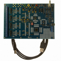
CDB5376
Description
EVALUATION BOARD FOR CS5376
Manufacturer
Cirrus Logic Inc
Datasheets
1.CS5371A-ISZR.pdf
(32 pages)
2.CS4373A-ISZ.pdf
(34 pages)
3.CS5376A-IQZR.pdf
(106 pages)
4.CDB5378.pdf
(16 pages)
5.CDB5376.pdf
(80 pages)
6.CDB5376.pdf
(16 pages)
Specifications of CDB5376
Main Purpose
Seismic Evaluation System
Embedded
Yes, MCU, 8-Bit
Utilized Ic / Part
CS3301A, CS3302A, CS4373A, CS5372A, CS5376A
Primary Attributes
Quad Digital Filter
Secondary Attributes
Graphical User Interface, SPI™ & USB Interfaces
Processor To Be Evaluated
CS330x, CS4373A, CS537x
Interface Type
USB
Lead Free Status / RoHS Status
Contains lead / RoHS non-compliant
Lead Free Status / RoHS Status
Lead free / RoHS Compliant, Contains lead / RoHS non-compliant
Other names
598-1778


11.DIGITAL FILTER INITIALIZATION
The CS5376A digital filter consists of three multi-
stage sections: a three stage SINC filter, a two stage
FIR filter, and a two stage IIR filter.
To initialize the digital filter, FIR and IIR coeffi-
cient sets are selected using configuration com-
mands and the FILTCFG register (0x20) is written
to select the output filter stage, the output word
rate, and the number of enabled channels. The dig-
ital filter clock rate is selected by writing the CON-
FIG register (0x00).
11.1 Filter Coefficient Selection
Selection of SINC filter coefficients is not required
as they are selected automatically based on the pro-
grammed output word rate.
Digital filter FIR and IIR coefficients are selected
using the ‘Write FIR Coefficients’ and ‘Write IIR
Coefficients’, or the ‘Write ROM Coefficients’
configuration commands. When writing the FIR
and IIR coefficients from ROM, a data word selects
an on-chip coefficient set for each filter stage. Fig-
ure 22 shows the format of the coefficient selection
DS612F4
Modulator
512 kHz
Input
Correction
DC Offset
& Gain
SINC Filter
2 - 64000
FIR1
4
Figure 21. Digital Filter Stages
Output to High Speed Serial Data Port (SD Port)
FIR2
2
Output Rate 4000 SPS ~ 1 SPS
word, and the available coefficient sets for each se-
lection.
Characteristics of the on-chip digital filter coeffi-
cients are discussed in the ‘SINC Filter’, ‘FIR Fil-
ter’, and ‘IIR Filter’ sections of this data sheet.
11.2 Filter Configuration Options
Digital filter parameters are selected by bits in the
FILTCFG register (0x20), and the digital filter
clock rate is selected by bits in the CONFIG regis-
ter (0x00).
11.2.1 Output Filter Stage
The digital filter can output data following any
stage in the filter chain. The output filter stage is se-
lected by the FSEL bits in the FILTCFG register.
Taking data from the SINC or FIR1 filter stages re-
duces the overall decimation of the filter chain and
increases the output rate, as discussed in the fol-
lowing section. Taking data from FIR2, IIR1, IIR2,
or IIR3 results in data at the selected rate.
1st Order
IIR1
2nd Order
IIR2
CS5376A
41
Related parts for CDB5376
Image
Part Number
Description
Manufacturer
Datasheet
Request
R

Part Number:
Description:
Development Kit
Manufacturer:
Cirrus Logic Inc
Datasheet:
Part Number:
Description:
Development Kit
Manufacturer:
Cirrus Logic Inc
Datasheet:


Part Number:
Description:
High-efficiency PFC + Fluorescent Lamp Driver Reference Design
Manufacturer:
Cirrus Logic Inc
Datasheet:
Part Number:
Description:
Development Kit
Manufacturer:
Cirrus Logic Inc
Datasheet:
Part Number:
Description:
Development Kit
Manufacturer:
Cirrus Logic Inc
Datasheet:

Part Number:
Description:
Development Kit
Manufacturer:
Cirrus Logic Inc
Datasheet:
Part Number:
Description:
Development Kit
Manufacturer:
Cirrus Logic Inc
Datasheet:
Part Number:
Description:
Development Kit
Manufacturer:
Cirrus Logic Inc
Datasheet:
Part Number:
Description:
Development Kit
Manufacturer:
Cirrus Logic Inc
Datasheet:

Part Number:
Description:
EVALUATION BOARD FOR CS8427
Manufacturer:
Cirrus Logic Inc
Datasheet:

Part Number:
Description:
BOARD EVAL FOR CS8416 RCVR
Manufacturer:
Cirrus Logic Inc
Datasheet:

Part Number:
Description:
EVALUATION BOARD FOR CS8420
Manufacturer:
Cirrus Logic Inc
Datasheet:

Part Number:
Description:
KIT DEVELOPMENT EP9315 ARM9
Manufacturer:
Cirrus Logic Inc
Datasheet:

Part Number:
Description:
KIT DEVELOPMENT EP9302 ARM9
Manufacturer:
Cirrus Logic Inc
Datasheet: