CDB5376 Cirrus Logic Inc, CDB5376 Datasheet - Page 32
CDB5376
Manufacturer Part Number
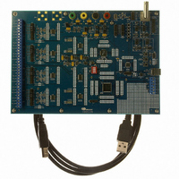
CDB5376
Description
EVALUATION BOARD FOR CS5376
Manufacturer
Cirrus Logic Inc
Datasheets
1.CS5371A-ISZR.pdf
(32 pages)
2.CS4373A-ISZ.pdf
(34 pages)
3.CS5376A-IQZR.pdf
(106 pages)
4.CDB5378.pdf
(16 pages)
5.CDB5376.pdf
(80 pages)
6.CDB5376.pdf
(16 pages)
Specifications of CDB5376
Main Purpose
Seismic Evaluation System
Embedded
Yes, MCU, 8-Bit
Utilized Ic / Part
CS3301A, CS3302A, CS4373A, CS5372A, CS5376A
Primary Attributes
Quad Digital Filter
Secondary Attributes
Graphical User Interface, SPI™ & USB Interfaces
Processor To Be Evaluated
CS330x, CS4373A, CS537x
Interface Type
USB
Lead Free Status / RoHS Status
Contains lead / RoHS non-compliant
Lead Free Status / RoHS Status
Lead free / RoHS Compliant, Contains lead / RoHS non-compliant
Other names
598-1778


9. CONFIGURATION BY MICROCONTROLLER
After reset, the CS5376A reads the state of the
BOOT pin to determine a source for configuration
commands. If BOOT is low, the CS5376A receives
configuration commands from a microcontroller.
9.1 Pin Descriptions
Pins required for microcontroller boot are listed
here, other SPI 1 pins are inactive.
SSI - Pin 49
Slave select input pin, active low. Serial chip select
input from a microcontroller.
SCK1 - Pin 48
Serial clock input pin. Serial clock input from mi-
crocontroller, maximum 4.096 MHz.
MOSI - Pin 51
Serial data input pin. Valid on rising edge of SCK1,
transition on falling edge.
MISO - Pin 50
Serial data output pin. Valid on rising edge of
SCK1, transition on falling edge. Open drain out-
put requiring a 10 kΩ pull-up resistor.
SINT - Pin 52
Serial interrupt output pin, active low. 1 uS active
low pulse output when ready for next serial trans-
action.
32
Digital Filter
Command
Interpreter
Figure 17. Serial Peripheral Interface 1 (SPI 1) Block Diagram
Registers
SPI 1
9.2 Microcontroller Hardware Interface
When booting from a microcontroller the
CS5376A SPI 1 port receives configuration com-
mands and configuration data through serial trans-
actions, as shown in Figure 18. 8-bit SPI opcodes
and 8-bit addresses are combined to read and write
24-bit configuration commands and data.
Microcontroller serial transactions require toggling
the SSI pin as the CS5376A chip select and writing
a serial clock to the SCK1 input. Serial data is input
to the CS5376A on the MOSI pin, and output from
the CS5376A on the MISO pin.
9.3 Microcontroller Serial Transactions
Microcontroller configuration commands are writ-
ten to the digital filter through the SPI 1 registers.
A 24-bit command and two 24-bit data words can
be written to the SPI 1 registers in any single serial
transaction. Some commands require additional
data words through additional serial transactions to
complete.
9.3.1 SPI opcodes
A
CS5376A SPI 1 port using standard 8-bit SPI op-
codes and an 8-bit SPI address. The standard SPI
‘Read’ and ‘Write’ opcodes are listed in Figure 18.
microcontroller
Pin Logic
SPI 1
SSI
SCK1
MOSI
SINT
communicates
MISO
CS5376A
with
DS612F4
the
Related parts for CDB5376
Image
Part Number
Description
Manufacturer
Datasheet
Request
R

Part Number:
Description:
Development Kit
Manufacturer:
Cirrus Logic Inc
Datasheet:
Part Number:
Description:
Development Kit
Manufacturer:
Cirrus Logic Inc
Datasheet:


Part Number:
Description:
High-efficiency PFC + Fluorescent Lamp Driver Reference Design
Manufacturer:
Cirrus Logic Inc
Datasheet:
Part Number:
Description:
Development Kit
Manufacturer:
Cirrus Logic Inc
Datasheet:
Part Number:
Description:
Development Kit
Manufacturer:
Cirrus Logic Inc
Datasheet:

Part Number:
Description:
Development Kit
Manufacturer:
Cirrus Logic Inc
Datasheet:
Part Number:
Description:
Development Kit
Manufacturer:
Cirrus Logic Inc
Datasheet:
Part Number:
Description:
Development Kit
Manufacturer:
Cirrus Logic Inc
Datasheet:
Part Number:
Description:
Development Kit
Manufacturer:
Cirrus Logic Inc
Datasheet:

Part Number:
Description:
EVALUATION BOARD FOR CS8427
Manufacturer:
Cirrus Logic Inc
Datasheet:

Part Number:
Description:
BOARD EVAL FOR CS8416 RCVR
Manufacturer:
Cirrus Logic Inc
Datasheet:

Part Number:
Description:
EVALUATION BOARD FOR CS8420
Manufacturer:
Cirrus Logic Inc
Datasheet:

Part Number:
Description:
KIT DEVELOPMENT EP9315 ARM9
Manufacturer:
Cirrus Logic Inc
Datasheet:

Part Number:
Description:
KIT DEVELOPMENT EP9302 ARM9
Manufacturer:
Cirrus Logic Inc
Datasheet: