CDB5376 Cirrus Logic Inc, CDB5376 Datasheet - Page 19
CDB5376
Manufacturer Part Number
CDB5376
Description
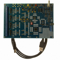
EVALUATION BOARD FOR CS5376
Manufacturer
Cirrus Logic Inc
Datasheets
1.CS5371A-ISZR.pdf
(32 pages)
2.CS4373A-ISZ.pdf
(34 pages)
3.CS5376A-IQZR.pdf
(106 pages)
4.CDB5378.pdf
(16 pages)
5.CDB5376.pdf
(80 pages)
6.CDB5376.pdf
(16 pages)
Specifications of CDB5376
Main Purpose
Seismic Evaluation System
Embedded
Yes, MCU, 8-Bit
Utilized Ic / Part
CS3301A, CS3302A, CS4373A, CS5372A, CS5376A
Primary Attributes
Quad Digital Filter
Secondary Attributes
Graphical User Interface, SPI™ & USB Interfaces
Processor To Be Evaluated
CS330x, CS4373A, CS537x
Interface Type
USB
Lead Free Status / RoHS Status
Contains lead / RoHS non-compliant
Lead Free Status / RoHS Status
Lead free / RoHS Compliant, Contains lead / RoHS non-compliant
Other names
598-1778


3. SYSTEM DESIGN WITH CS5376A
Figure 9 illustrates a simplified block diagram of
the CS5376A in a multi-channel measurement sys-
tem.
Up to four differential sensors are connected
through CS3301A/02A differential amplifiers to
the CS5371A/72A ∆Σ modulators, where analog to
digital conversion occurs. Each modulators 1-bit
output connects to a CS5376A MDATA input,
where the oversampled ∆Σ data is decimated and
filtered to 24-bit output samples at a programmed
output rate. These output samples are buffered in
an 8-deep data FIFO and passed to the system te-
lemetry on command.
System self tests are performed by connecting the
CS5376A test bit stream (TBS) generator to the
CS4373A test DAC. Analog tests drive differential
signals from the CS4373A test DAC into the mul-
tiplexed inputs of the CS3301A/02A amplifiers or
DS612F4
Hydrophone
Hydrophone
Hydrophone
Hydrophone
Geophone
Geophone
Geophone
Geophone
Sensor
Sensor
Sensor
Sensor
or
or
or
or
M
U
M
U
X
X
M
U
X
M
U
X
Figure 9. Multi-Channel System Block Diagram
AMP
AMP
AMP
AMP
CS3301A
CS3302A
CS3301A
CS3302A
CS3301A
CS3302A
CS3301A
CS3302A
Switch
Switch
MUX
MUX
Modulator
Modulator
CS5371A
CS5372A
CS5371A
CS5372A
∆Σ
∆Σ
directly to the sensors through external analog
switches. Digital loopback tests internally connect
the TBS digital output directly to the CS5376A
modulator inputs.
3.1 Power Supplies
The multi-channel system shown in Figure 9 typi-
cally operates from a
and a 3.3 V digital power supply. The CS5376A
logic core can be powered from 3 V to minimize
power consumption, if required.
3.2 Reset Control
System reset is required only for the CS5376A de-
vice, and is a standard active low signal that can be
generated by a power supply monitor or microcon-
troller. Other system devices default to a power-
down state when the CS5376A is reset.
CS5376A
Digital Filter
CS4373A
DAC
Test
±
2.5 V analog power supply
System Telemetry
Communication
Configuration
µController
EEPROM
Interface
CS5376A
or
19
Related parts for CDB5376
Image
Part Number
Description
Manufacturer
Datasheet
Request
R

Part Number:
Description:
Development Kit
Manufacturer:
Cirrus Logic Inc
Datasheet:
Part Number:
Description:
Development Kit
Manufacturer:
Cirrus Logic Inc
Datasheet:


Part Number:
Description:
High-efficiency PFC + Fluorescent Lamp Driver Reference Design
Manufacturer:
Cirrus Logic Inc
Datasheet:
Part Number:
Description:
Development Kit
Manufacturer:
Cirrus Logic Inc
Datasheet:
Part Number:
Description:
Development Kit
Manufacturer:
Cirrus Logic Inc
Datasheet:

Part Number:
Description:
Development Kit
Manufacturer:
Cirrus Logic Inc
Datasheet:
Part Number:
Description:
Development Kit
Manufacturer:
Cirrus Logic Inc
Datasheet:
Part Number:
Description:
Development Kit
Manufacturer:
Cirrus Logic Inc
Datasheet:
Part Number:
Description:
Development Kit
Manufacturer:
Cirrus Logic Inc
Datasheet:

Part Number:
Description:
EVALUATION BOARD FOR CS8427
Manufacturer:
Cirrus Logic Inc
Datasheet:

Part Number:
Description:
BOARD EVAL FOR CS8416 RCVR
Manufacturer:
Cirrus Logic Inc
Datasheet:

Part Number:
Description:
EVALUATION BOARD FOR CS8420
Manufacturer:
Cirrus Logic Inc
Datasheet:

Part Number:
Description:
KIT DEVELOPMENT EP9315 ARM9
Manufacturer:
Cirrus Logic Inc
Datasheet:

Part Number:
Description:
KIT DEVELOPMENT EP9302 ARM9
Manufacturer:
Cirrus Logic Inc
Datasheet: